NATIONAL UNIVERSITY OF CIVIL ENGINEERING
DIVISION OF CONSTRUCTION TECHNOLOGY AND MANAGEMENT
CONSTRUCTION TECHNOLOGY II PROJECT
Requirement: Design assembly method for Industrial building using
prefabricated elements
Instructor
Student
Class
Student ID
VUONG DO TUAN CUONG
55XE
Hanoi, 11/2014
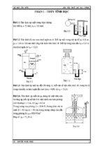
I.
ANALYZING TYPICAL FIGURES OF THE BUILDING
One-storey industrial building with 2 spans and 13 frames constructed by assembly method
from a range of different structure members including concrete columns, roof and wall panels,
crane runway beams, concrete roof frames, and opening windows. These components have
already been fabricated in factories, then delivered to construction site for installing.
Length of building: 12x6 = 72 (m), so there should be one settlement joint.
Width of building: L = 2 x 18 = 36 (m).
1.
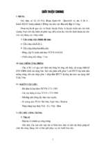
Building cross-section:
BUILDING CROSS SECTION
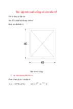
BUIDLING PLAN
2.
Structure parameters:
General Information
Number of storeys
1
Number of spans
2
Number of column: A;B;C;D
13
Side-columns
Concrete columns
Middle columns
Concrete roof frame
Crane runway beam
H(m)
13.3
h(m)
10.0
W(T)
7.8
H(m)
13.3
h(m)
10.0
W(T)
8.7
L(m)
18
a(m)
2.45
W(T)
5.0
L(m)
6
h(m)
0.8
W(T)
3.3
Opening window
Roof and wall panel
l(m)
6
b(m)
2.6
W(T)
1.2
Dimension(m)
3x6
W(T)
2.3
II.
SELECTING EQUIPMENTS:
1. Selecting hanging and tying equipments:
1.1.
Columns:
Columns is light and have brackets => use steel cable and friction belt to hang them
vertically.
a) Middle columns:
Tensile force is calculated by the formula:
Ptt
S k
m n cosβ
Qct
S
Legend:
k – Safety ratio, k = 6
Ptt 1.18.7 9.57 T
β - Inclined angle of cable and vertical direction, β=00
m - Ratio related to the difference in the value of tensile force
within the two branches of cable, m=1
n - Number of steel cable, n=2
9.57
28.71 T
=> S 6
12 Cos 0
Selecting cable 6x37x1 with diameter D=26mm, tensile strength (140kg/cm2), failure force
F= 29000 (kg)
Cable weight: γ=2.38 kg/m
Length of each steel cable: lbc= 1.5 + 3.3 = 4.8 (m)
Frictional belt weight: qfb=30 kg
Weight of hanging and tying equipment:
qe 2 lbc q fb 2 2.38 4.8 30 52.85 kg
b) Side-columns (C1)
Tensile force is calculated by the formula:
Ptt
S k
m n cosβ
Qct
S
Legend:
k – Safety ratio, k = 6
Ptt 1.17.8 8.58 T
β - Inclined angle of cable and vertical direction, β=00
m - Ratio related to the difference in the value of tensile force
within the two branches of cable, m=1
n - Number of steel cable, n=2
8.58
25.74 T
=> S 6
12 Cos0
Selecting cable 6x37x1 with diameter D=26mm, tensile strength (140kg/cm2), failure force
F= 29000 (kg)
Cable weight: γ=2.38 kg/m
Length of each branch of steel cable: lbc= 1.5 + 3.3 = 4.8 (m)
Frictional belt weight: qfb=30 kg
Weight of equipment for hanging and tying:
qe 2 lbc q fb 2 2.38 4.8 30 52.85 kg
1.2.
Crane runway beam
Crane runway beam (CRB) is a structure member working in horizontal direction, so we
choose an ordinary equipment for hanging and tying with semi-automatic lock. The way how
to hang and tie is shown in the following figure
where:
1- Steel cushion block
2- Steel cable
3- Semi-automatic lock
4- Pipe section for inserting cable
Crane runway beam (CRB) is a structure member working in horizontal direction, so we
choose an ordinary equipment for hanging and tying with semi-automatic lock.
Tensile force of cable is determined by the below formula:
Ptt
S k
m n cosβ
Legend:
k – Safety ratio, k = 6
Ptt 1.13.3 3.63 T
β - Inclined angle of cable and vertical direction, β=450
m - Ratio related to the difference in the value of tensile force within the
two branches of cable, m=1
n - Number of steel cable, n=2
3.63
15.4 T
=> S 6
12 Cos 45
Selecting cable 6x37x1 with diameter D=17,5 mm, tensile strength (140 kg/cm2), failure
force F= 12750 (kg)
Length of each branch of steel cable: l= 1.5 + 2.4/Cos(45) = 4.89 (m)
Cable weight: γ=1.06 kg/m
Frictional belt weight: qfb=30kg
Weight of equipment for hanging and tying
qe = γ.l + qfb= 1.06 x 4.89 x 2 + 30 x 2= 70.84 kg = 0.071 T
1.3.
Concrete roof panels:
Panels have 2 dimesions 3x6 (m) with the weigh of 2.3 T ,we use four steel cables with a
self-balacing ring.
Tensile force in each cable is calculated by:
Ptt
S k
m n cosβ
Ptt 1.12.3 2.53 T
m=0,75 (four cables-branches)
n=4
β= 450 (for safety purpose, calculate with β=450)
2.53
7.16 T
0, 75 4 cos 45
=> S 6
Selecting cable 6x37x1 with diameter D=13mm, tensile strength (140kg/cm2), failure
force F= 7200 (kg)
Length of each steel cable: l= 6 (m)
Cable weight: γ=0.59 kg/m)
Weight of equipment for lifting:
qe= 0.59 x 6 x 4= 14.2 (kg) = 0,01 (T)
1.4.
Concrete wall panels:
Panels have 2 dimesions 3x6 (m) with the weight of 2.3T ,we use a cluster of two
cables with a self-balacing ring.
steel
Tensile force in each cable is calculated by:
Ptt
S k
m n cos β
Ptt 1.12.3 2.53 T
m=1
n=2
β= 450 (acctually β do not equal to 450,but higher. However, for safety
reason, calculate with β=450)
2.53
10.73 T
12 cos 45
=> S 6
Selecting cable 6x37x1 with diameter D=17.5mm, tensile strength (140kg/cm2), failure
force F= 12750 (kg)
Length of each steel cable: l= 4.5 (m)
Cable weight: γ=1.06 (kg/m)
Weight of equipment for lifting:
qe= 4.5 x 1.06 x 2= 9.54 (kg) = 0,01 (T)
1.5.
Steel frame:
Because contructing these components at high place, steel roof frames need to be preerected on the ground in order to ensure safety and then be hanged and installed
simultaneously. Tools for hanging and tying are equipped semi-automatic lock and selfbalancing ring.
The steel roof frames have long span, so hanging bar is used to assist the process of
erecting. Supported positions are chosen at joints of frames to avoid moment and shear force
appearing within frames.
The steel roof frames have L=18m in length, we choose hanging bar with code 195946R11 ( [Q]= 10T, G=0,455 (T)
The tensile force in each branch of two cables is determined by the below formula:
Ptt
S k
m n cosβ
Legend:
Ptt= 1,1.P= 1.1 x (5+1.2)= 6.82 (T)
n= 2
m= 1
β=30o
6.82
23.63 T
1 2 cos300
S 6
Selecting cable 6x37x1 with diameter D=24 mm, tensile strength (140 kg/cm2), failure
force F= 24300 (kg)
Length of each branch of steel cable l= 5.0 (m)
Frictional belt weight: qfb=30 kg
Cable weight: γ=1.99 kg/m
Weight of lifting equipment
qe= γ.l + qfb+ G= 1.99 x 5 x 2 + 30 x 2 + 455= 534.9 (kg) = 0.53 (T)
2. Lifting and installing data calculation:
Selecting crane tower base on the following parameters:
Hrq – height of hook
Lrq - length of working jib
Qrq - lifting capacity
Rrq - working radius
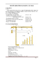
2.1. Calculating lifting & installing data of column
Assembling column without obstacles
=> working jib with αmax = 750
a) Middle columns:
Lifting capacity :
Qrq = Ptt + qe = 9.57 + 0.05= 9.62 T
Using geometric method we have crane data diagram :
Requirement height:
Hrq = HL + a + hm + he + hh
With :
HL: height to install element HL = 0
a : distance from ground to height of lifting cable a = 0.5 m
hm : height of element hm = 13.3 m
he : length of lifting cable he = 1.5 m
hh : height of pulley, hook hh = 3.47 m
H rq 0 0.5 13.3 1.5 3.47 18.77(m)
Jib length :
H rq hc
18.77 1.5
17.80(m)
sin 75
sin 750
Where: hc – level of the slewing ring of the crane (from the ground surface).
Lrq
0
Working radius of jib :
S Lmin cos 75 17.8 cos 75 4.6(m)
Minimum working radius of crane:
Rrq = S + r
Rrq 4.6 1.5 6.1 m
b) Side-columns:
Lifting capacity: Qrq = Ptt + qe = 8.58 + 0.05 = 8.63 T
Requirement height:
Hrq = HL + a + hm + he + hh
With :
HL: height to install element HL = 0
a : distance from ground to height of lifting cable a = 0.5 m
hm : height of element hm = 13.3 m
he : length of lifting cable he = 3.47 m
hh : height of pulley, hook hh = 3.47 m
H rq 0 0.5 13.3 1.5 3.47 18.77(m)
Jib length :
H rq hc
18.77 1.5
17.80(m)
sin 75
sin 750
Where: hc – level of the slewing ring of the crane (from the ground surface).
Lrq
0
Working radius of jib :
S Lmin cos 75 17.8 cos 75 4.6(m)
Minimum working radius of crane:
Rrq = S + r
Rrq 4.6 1.5 6.1 m
2.2. Calculating lifting & installing data of crane runway beam
Assembling of crane runway beam without obstacles
=> Select working jib follow : αmax = 750
Lifting capacity : Qrq = Ptt + qe = 3.63+ 0.07 = 3.7 T
Requirement height:
Hrq = HL + a + hm + he + hh
With :
HL: height to install element HL = 10 – 0.7 = 9.3 m
a : height of lifting element a = 0.5 m
hm : height of element hm = 0.8 m
he : length of lifting cable he = 2.4 m
hh : height of pulley, hook hh = 1.5 m
H rq 9.3 0.5 0.8 2.4 1.5 14.5( m)
Working radius :
Lrq
H rq hc
sin 750
With hc – level of the slewing ring of the crane (from the ground surface).
14.5 1.5
Lmin
13.45(m)
sin 750
Working radius of jib :
S = Lmin x cos750 = 13.45 x cos750 = 3.48 m
Minimum working radius of crane:
Rrq = S + r
Rrq 3.4 1.5 4.98(m)
2.3. Calculating lifting & installing data of roof frame and opening window:
Assembling of crane runway beam without obstacles so we choose working jib as follow :
αmax = 750
Lifting capacity :
Qrq = Wm + qe = 1.1( Prf + Pow ) + qe = 6.82 + 0.53 = 7.35 T
Requirement height of hook :
Hrq = HL + a + hm + he + hh
With :
HL: height to install element HL = 13.3 – 0.7 = 12.6 m
a : height of lifting element a = 0.5 m
hm : height of element hm = 2.45 + 2.6 = 5.05 m
he : length of lifting cable he = 1 m
hh : height of pulley, hook hh = 1,5 m
H rq 12.6 0.5 5.05 1 1.5 20.65(m)
Working radius :
Lrq
H rq hc
sin 750
With hc – level of the slewing ring of the crane (from the ground surface).
20.65 1.5
Lmin
19.93( m)
sin 750
Working radius of jib :
S = Lmin x cos750 = 19.93 x cos750 = 5.16 m
Minimum working radius of crane:
Rrq = S + r
Rrq 5.16 1.5 6.66( m)
2.4. Calculating lifting & installing data of roof panel
Without fly jib HL = 17.75 m
-0.3
Lifting capacity :
Qrq = Ptt + qe = 2.53 + 0.01 = 2.54 T
Requirement height of hook :
Hrq = HL + a + hm + he + hh
With :
HL: height to install element HL = 13,3 – 0.7 + 2.45 + 2.6 = 17.75 m
a : height of lifting element a = 0.5 m
hm : height of element hm = 0.4 m
he : length of lifting cable he = 6cos(45)=4.24 m
hh : height of pulley, hook hh = 1,5 m
H rq 17.75 0.5 0.4 4.24 1.5 24.39(m)
Hch = HL + a + hm = 17.75 + 0.5 + 0.4 = 18.65 m
Best jib angle :
H h
18.65 1,5
tw arctg 3 ch c = arctg 3
58.390
e b
1 3
Working radius :
H ch hc
e b
0
sin 58.39 cos 58.390
With hc – level of the slewing ring of the crane (from the ground surface).
Lrq
18.65 1.5 1 3
Lmin
27.79( m)
0,851
0,524
Working radius of jib :
18.65 1.5
S
cos 58.390 10.55(m)
0
sin 58.39
Minimum working radius of crane:
Rrq = S + r
Rrq 10.55 155 12.05(m)
Using fly jib αmax = 750
-0.3
tw arctg 3
H ch hc
750
'
e b l
l ' 3.67m
l’ = lmcos300 ( inclination angle between fly jib and horizontal direction)
Working radius :
H ch hc e b l '
sin 750
cos 750
With hc – level of the slewing ring of the crane (from the ground surface)..
Lrq
18.65 1.5 1 3 3.67
Lmin
19.03(m)
0.966
0.259
Working radius of jib :
19.03 1.5
S
cos 750 3 1 8.70( m)
0
sin 75
Minimum working radius of crane:
Rrq = S + r
Rrq 8.70 1.5 10.2( m)
2.4. Calculating lifting & installing data of wall panel
Assembling of crane runway beam without obstacles
=> Select working jib follow : αmax = 750
Lifting capacity : Qrq = Ptt + qe = 2.53+ 0.01 = 2.54 T
Requirement height:
Hrq = HL + a + hm + he + hh
With :
HL: height to install element HL = 13.3– 0.7 =12.6 m
a : height of lifting element a = 0.5 m
- Xem thêm -