273
Chapter 10: Designing Millimeter-Wave Devices
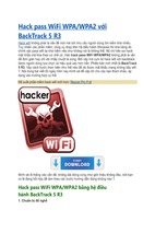
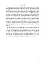
Figure 10-2
Integrated hybrid
millimeter-wave, fiber,
and optical wireless
data access and distribution system scenarios.
Implementation
options for integrated
HFR for picocell access
and distribution
systems for inner city
environments and
interconnection
options. (Note: The
World Trade Center
towers in New York
City are shown in this
figure to remember
those who died in the
terrorist attack of
September 11, 2001.)
Millimeterwave links
FSOW
links
Neighborhood
microcell
AP
AP
Building picocell
Fiber/coax
Picocell redistribution: outdoor and/or
indoor by wireless, fiber, or coax
The possibility of using the existing embedded fibers to the curb and
neighborhood as well as FSOW tandem links permits broadband backbone network integration and combined services through a single shared
infrastructure, leading to faster deployment and lower system cost for service providers.
Network Operation Center
A consolidated network operation center (NOC) for end-to-end network
management and control is implemented to relocate the conventional
base station control and switching facilities into the NOC to perform the
required switching, routing, and service-mixing-function operations. The
integration and merging of multiband HFR, FSOW, and digital fiberoptic technologies at the NOC with fixed BWA has provided flexible and
unified network operation as well as the possibility of end-to-end network
management and control. The consolidation will benefit through lower
infrastructure complexity and cost, resulting in a more reliable and centralized database and operations.
274
Part 2:
Planning and Designing Data Applications
Portable Broadband Wireless Data
Bridge and Access Node
This chapter will now discuss the concept and realization of a portable
wireless data access node for a bidirectional ATM-based connection to
reach a fixed broadband fiber network. The goal of this effort is to demonstrate the feasibility of a rapidly deployed access node and backbone
interconnection to the NOC for application in specialized scenarios, such
as military theaters, emergency response, and disaster relief operations.
Two portable nodes could also serve as a point-to-point wireless bridge
to connect two or more isolated networks in places not served by fibers,
as depicted in the lower left corner of Fig. 10-1.
Free-Space Optical Wireless Data
Access and High-Speed Backbone
Reach Extension
This is an emerging advanced technology providing many new approaches
and platforms for high-bandwidth wireless data access and distribution
networks. The technology, in combination with the millimeter-wave network topology, has created potential for increased capacity and extended
the fiber-based bandwidth and services to users via wireless data. In the
demonstrator, an FSOW point-to-point link is employed to complement
and extend the NGI wireless data access capabilities for true gigabit-persecond data transport. The combined and side-by-side millimeterwave/FSOW hybrid network topology shown in Fig. 10-1 provides direct
performance comparison with the millimeter-wave links in various environmental conditions (multipath, rain fade) required for the design and
implementation of high-reliability networks. Moreover, this topology
ensures a higher degree of link availability when the millimeter wave
fails during the rain or the FSOW power budget falls below the specified
threshold during foggy weather. It has been shown that the hybrid technology can increase the current millimeter-wave network capacity and
high-speed data transport capabilities.
A Measurement-Based Channel Model
To investigate millimeter-wave propagation issues, a high-resolution
channel sounder at the 38-GHz LMDS band to model the channel on the
Chapter 10: Designing Millimeter-Wave Devices
275
basis of the measurements and simulation results is used. The model
addresses the performance limits for broadband point-to-multipoint
wireless data access in terms of data transport capability under realistic
commercial deployment conditions. The model is used to examine a
broadband channel-adaptive radio modem for dynamic selection of channel quality, channel switching, and bandwidth allocations. Propagation
characterization, modeling, and simulation were performed for a shortrange BWA system to provide sight selection design rules and solutions
for adaptive channel configuration and operation mechanisms. A set of
comprehensive data processing tools has been developed that, in combination with the channel sounder, can be used to develop statistical models
for the broadband millimeter-wave channels.
System Architecture Advantages
Compared to the traditional LMDS system, the system technology and
heterogeneous network topology previously described possess many technological and operational advantages:
Increased coverage and user penetration percentage in each
individual cell due to densely positioned users in the service area.
This relaxes the tedious effort of cell frequency and polarization
reuse planning.
This in turn leads to a simpler design of overlapping cells for higher
coverage and permits more efficient utilization of the spectrum.
The required AP hub and customer transmitting power (at
millimeter wave) are immediately scaled down (15 dB minimum)
because of the relatively short cell radius. The result is a low-power,
low-cost system solution and less complex MMIC hardware design.
A major reduction in system interference (adjacent channel and
adjacent cell) comes from constraints and limitations imposed by
the power amplifiers’ nonlinearities in high-power systems, due to
spectral regrowth.
As a result, possible reduction in the required radio channel
spacing can be achieved, leading to increased system capacity due
to higher spectrum utilization and efficiency.
The near-short-range directly projected line-of-sight (LOS)
propagation path becomes free from “major” multipath
interference, intercell interference, and obstructions (buildings,
moving objects, trees, and foliage). Consequently, the propagation
path loss approaches that of square law, leading to a power-efficient
system.
276
Part 2:
Planning and Designing Data Applications
An additional improvement in the system gain margin (7 to 10 dB)
and link availability comes from the short LOS distance that
removes the signal reception limitation due to excessive rain
attenuation and system downtime experienced in higher-power,
longer-range LMDS systems.
The utilization of a hybrid millimeter-wave/FSOW network
topology extends the broadband network reach without utilizing
the radio spectrum. It can also provide high-capacity links,
increased frequency reuse of millimeter waves, and greatly
enhanced network reliability and availability.1
Implementation and Test Results
Now, let’s look at the implementation of experimental BWA links and an
asynchronous transfer mode (ATM)–based networked testbed infrastructure for experimentation toward high-speed Internet applications and
W-WLL performance evaluation. The testbed comprises a single AP and
three user nodes (two fixed and one portable), as shown in Figs. 10-3
and 10-4, operating in the 5.8/28/38-GHz bands.1 A side-by-side highspeed point-to-point FSOW link (see Fig. 10-1), in parallel or tandem,
was also implemented to extend the backbone fiber bandwidth to the AP
operating up to 622-Mbps rates. On all the links, network demonstrations have been carried out for mixed services: broadcast 80-channel
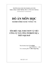
Figure 10-3
Multiband multiuser
BWA testbed
configurations.
Data
Internet
Fiber-optic connection
Network
operations
center
Satellite broadcast
receiver
Video
User A ODU
28 GHz
38 GHz
28 GHz
Access point
User B IDU
Data
Decoded 32-QAM data
Com
Video
eo
d vid
ta an
da
bined
User B ODU
User A IDU
277
Chapter 10: Designing Millimeter-Wave Devices
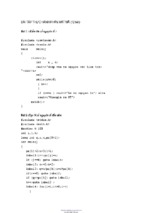
• OC-3 duplex transmission
• Separation between nodes = 470 m
• Transmit power = –10 dBm
• BER < 10–9
• Link established within 20° of hub antenna LOS
• Configuration suitable for point-to-multipoint operation
FSOW
Trx
Rcv
MMW
Trx
Portable node
0
Received power (dB)
Figure 10-4
Portable node experimentation and measured BER.
–10
–20
–30
Hub unit on hillside
–40
0
5
10
15 20
Angle from boresight (degrees)
Power received at portable node
Portable and FSOW nodes
video and RF wireless data channels with speeds at 1.5-, 25-, 45-, and 155
(OC-3)–Mbps rates in 4-, 16-, 32-, or 64-quadrature amplitude modulation (QAM) formats. The key issue in the topology described here is that
the AP transmitter has the low power practical for mass deployments.
The implemented portable node of Fig. 10-4 is equipped with an OC-3
connection that occupies 50 MHz of bandwidth for 16 QAM. The performance of the OC-3 portable node was also field-tested using a data
stream supplied by either a bit error test set or an Internet advisor ATM
analyzer. Error-free operation was achieved in a 20° sector of a 470-m
microcell environment.
Figure 10-5 depicts the functional elements and interconnection in the
ATM-based BWA and distribution network in the NOC.1 The ATM switch
is programmed to combine and distribute traffic, integrate mixed services,
and create dynamic user interconnection paths. The combined ATM wireless data/fiber network operation, as well as service integration, has been
evaluated and tested using an Internet advisor ATM analyzer. Error-free
millimeter-wave/optical transmission and network operation were
achieved for 155-Mbps data channels switched between three users in
cells up to 470 m in radius.
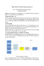
Figure 10-6 illustrates several examples of integrated HFR and RF
photonics for wireless data/fiber internetworking and interface options.1
The advantage of microwave and RF photonics is that it not only
expands and merges broadband distribution and access, but it also incorporates “networked” functionality and control into the wireless data
links. The top figure indicates integration of several different wireless
278
Figure 10-5
A three-user testbed
and ATM network
topology.
Part 2:
Planning and Designing Data Applications
Hub
EO/OE
Portable hub
NOC
NOC and control
center
UTP
ATM
OC3
Portable node
To backbone
ATM
OC3
SM to MM
converter
DS3
Modem Modem Modem
Users
ATM
Multi-IF HFR
connection
EO/OE
OC3
OC3
Modem
Modem
OC3 Modem
Ethernet hub
Hub
5.8-GHz
wireless
LAN
data bands (PCS, NII, millimeter-wave, FSOP) into a single HFR using
WDM technology. The system integration has also been demonstrated for
a single optical wavelength and synchronized multicarrier millimeterwave radios with modular IF stages. The millimeter-wave subcarriers
are selected with one-to-one fiber/wireless data channel mapping to provide
unified end-to-end network operation and continuity.
The lower left part of Fig. 10-6 depicts the role of HFR for multiple
AP signal distribution, centralized control of individual antenna beam
and phases, and frequency band selections. Here, the otherwise traditional “antenna remoting” function has been replaced by a multiple service access link with centralized network management and control.
The lower right part of Fig. 10-6 depicts yet another example—utilizing
the HFR technology to distribute high-stability, low-phase-noise local
oscillator (LO) and sync signals to the millimeter-wave up/downconverters
in the APs and base terminals. The experimentally deployed LO distribution demonstrated lower harmonics and superior phase quality in
millimeter-wave systems, as well as lowered electrical intermediate frequency (IF)/RF terminal design complexity, component counts, and overall cost compared to pure all-electrical solutions. A two-channel (12- and
16-GHz) photonic unit was demonstrated for evaluating the performance of a switched dual-band photonic link in distributing LO/sync signals. The scheme provides the flexibility of frequency tuning, channel
selection, and dynamic bandwidth allocations for wireless data access
systems.
279
Beam
steering
LO
gen
Local
•
•
•
•
AP
Distributed antenna remoting
Reception from multiple picocells
Photonic up/down conversion
Coherent combining using photonics
Hybrid fiber radio
AP
AP
mux
Network
operation
center
•
•
•
•
2 GHz
LO
X
Mixer
x12
Large multiplicative phase noise
Difficult filtering requirements
Design complexity
Independent LOs in system
Filter
Data on
subcarriers
•
•
•
•
A
N
T
8-GHz
LO
X3
A
N
T
Antenna
Lower phase noise
Coherent LO distribution
Simplified filtering
Centralized functional management
Demux
Data on
subcarriers
Mixer
WDM
fiber network
Laser
Mixed analog and digital signals and mixed service capabilities
Laser
array
Switched beam
antenna
Multiband
RCVs
Radio on fiber hub
ROF and hybrid fiber radio
internetworking topology
Figure 10-6 Multiband ROF and HFR interconnection examples for a unified end-toend network. Top: the role of WDM and RF photonics in a wireless data/fiber network
interface. Lower left: multiple AP signal distribution and control. Lower right: centralized high-stability low-phase-noise LO distributed to the APs and base terminals.
Broadband
interactive services
IP
router
Wireless
routers
Broadcast
services
PCS
NII
ISM
MMW
Access radios
Multi-users in
single or multiband
280
Part 2:
Planning and Designing Data Applications
Conclusion
This chapter has introduced and demonstrated a short-range LOS
LMDS-like millimeter-wave and FSOW architecture for a BWA system
that possesses many technological and operational advantages. These
include ease of installation and alignment; low radiation power; and,
effectively, a link free from major multipath, obstructions (trees, buildings, and moving objects), and adjacent cell interference. The chapter
also presented several system architecture and implementation scenarios for a complementary millimeter-wave/FSOW system highly suitable
for integration of a BWA network with the existing backbone fiber network. The proposed system architecture is suitable for deployment in a
highly developed, densely populated, urban inner city environment where
large-capacity broadband services are in great demand, but lacking
wired broadband access infrastructure.
References
1. Hossein Izadpanah, “A Millimeter-Wave Broadband Wireless Access
Technology Demonstrator for the Next-Generation Internet Network
Reach Extension,” IEEE Communications Magazine, 445 Hoes Lane,
Piscataway, NJ 08855, 2002.
2. John R. Vacca, Wireless Broadband Networks Handbook, McGraw-Hill,
2001.
3. John R. Vacca, Satellite Encryption, Academic Press, 1999.
4. John R. Vacca, i-mode Crash Course, McGraw-Hill, 2001.
11
Wireless Data
CHAPTER
Services:
The Designing
of the
Broadband Era
Copyright 2003 by The McGraw-Hill Companies, Inc. Click Here for Terms of Use.
282
Part 2:
Planning and Designing Data Applications
Loose coalitions of tech geeks, amateur radio hobbyists, and social
activists worldwide have begun to design free broadband wireless data
networks.3 Sit in a park or cafe near one of these networks with your
laptop and modem, and you can access files on your home or office computer, or access the Web without a hard-wired connection.
While some of these broadband wireless data networks are designed
to extend free Internet access to people who otherwise couldn’t afford
the service, others are building what amounts to a community intranet.
It’s not about Internet access. It’s about building up a broadband wireless data network, connecting people through their computers in the
community.
The broadband wireless data networks are based on the 802.11b wireless data networking standard. Participants purchase access points,
then create or buy antennas and place them on the roofs of their houses
or apartment buildings and become nodes on a broadband wireless data
network that links members’ computers together. Many members with
antennas already have high-speed data lines, such as DSL or cable
modems, and they can share that Internet access for free with anyone
who has an 802.11b modem and is within range of an access point. (The
Glossary defines many technical terms, abbreviations, and acronyms used
in the book.)
A growing number of local businesses will raise antennas and join the
broadband wireless data network as a way to establish a presence among
the other users of the network. A couple of coffee shops in Seattle are
already part of SeattleWireless’ data network, which so far has nine
nodes.
As more people join the broadband wireless data network, the community grows and gives more impetus for businesses, for example, to
maintain sites on the community network for free. Instead of paying a
recurring monthly fee for a Web site, members incur only the one-time
cost of putting up an antenna and linking to the broadband wireless
data network.
Other businesses may want to add nodes on the broadband wireless
data network so workers can access the corporate network from home or
nearby cafes or restaurants. The broadband wireless data network doesn’t
have to hit the public Internet, and can use virtual private network technology to tunnel securely into the corporate intranet.
The independent way the broadband wireless data networks grow,
however, may be one of the drawbacks.
Chapter 11: Wireless Data Services
283
Word Spreads
These volunteer projects seem to grow in fits and starts, yet the momentum in Seattle has spread quickly outside the city. Seattle is the pioneer
in doing this in the world.
The idea is to have an independent broadband wireless data network.
If the Internet backbone goes down, this will act as a network that
would still be up in an emergency.
These groups run the risk of angering ISPs that might not like the
fact that some of their network users are accessing the Internet without
paying. So far, leaders of the free wireless data groups believe that they
are just a blip on the ISPs’ radar and not worth worrying about.
That may be true among the more open-minded ISPs. If some people
are experimenting with cool stuff, there won’t be a problem.
Most ISPs aren’t happy to learn that customers are sharing connections for free, but the practice isn’t expected to blossom to a threatening
size. The problem with grass-roots local-area networks (LANs) is that
someone has to pay for that service, and the reliability and performance
of the link will be limited because no one has the incentive to invest
additional dollars.
That fact may slow the growth of the free broadband wireless data
networks and affect the networks’ quality, but it also preserves the market for customers that might be willing to pay for the assurance of quality
service. For example, MobileStar Network is one well-known company
using 802.11b in places such as Starbucks coffee shops to offer highspeed wireless data Internet access to paying subscribers. The company
has backup measures in place to ensure that customers receive highquality service, and indicates that assurance will continue to attract customers.
However, some DSL and cable modem service providers may have reason to complain. High-speed data providers oversubscribe on the basis of
projections of how much bandwidth customers will use. An unexpected
number of users on their networks could affect their business plans. The
network providers are concerned about maintaining the bandwidth they
have.
Now, let’s look at how typical image compression algorithms produce
data streams that require a very reliable communication—they are not
designed for transmission in an environment in which data may be lost
or delayed, as provided by current and next-generation broadband
284
Part 2:
Planning and Designing Data Applications
wireless data communication networks. Compression and transmission
provisions that avoid catastrophic failure caused by lost, delayed, or errant
packets are therefore imperative in order to provide reliable visual communication over such systems. This robustness is obtained by modifying
the source coding and/or adding channel coding. This part of the chapter
presents an overview of both lossy and lossless source coding techniques
and combined source/channel techniques providing robustness, examples
of successful techniques.
Wireless Data Channel Image
Communications
Images contain a great deal of redundancy, from both signal processing
and psychological perspectives, which effective compression attempts to
remove. Typical image compression algorithms produce data streams
that require a very reliable and in fact perfect communication channel—
they are not designed for transmission in an environment in which data
may be lost or delayed (in real-time imaging, delay is equivalent to loss).
Broadband wireless data systems are characterized by their limited
bandwidths and high bit error rates, and cannot provide the necessary
quality of service guarantees for compressed image data; therefore, compression and transmission provisions that avoid catastrophic failure
caused by lost, delayed, or errant packets are imperative. Robustness is
obtained by modifying the source coding and/or adding channel coding.
Source coding can be modified by increasing redundancy in the image
representation and making the encoded bit stream itself more robust to
errors (while the former typically increases the source data rate, the latter can often be obtained with minimal or no increase in source data
rate). Channel coding adds controlled redundancy in exchange for source
coding rate. When combined, the required robustness can be provided
for many broadband wireless data environments.
To appropriately understand the image transmission issue, first consider two extremes of image transmission over unreliable channels that
allow lost or errant data to be recovered from received data. The first
extreme is an information-theory result given by Shannon’s well-known
joint source/channel coding theorem: A stochastic process can be optimally transmitted over a channel if the source coding and channel coding are performed independently and optimally. Zero redundancy is
placed in the source coding, and maximum redundancy is placed in the
channel coding. Recovery from transmission errors is possible, provided
that restrictions placed by the channel coding on the errors are not
exceeded.
Chapter 11: Wireless Data Services
285
NOTE Knowledge of the channel is required to select an appropriate
channel code.
A second hypothetical extreme exists in which knowledge of the channel is not required to ensure reliable image transmission. The uncoded
image is simply transmitted, and the redundancy present in the image
is used to compensate for lost data. In this case, raw data can be corrupted, but an uncoded image has sufficient redundancy to allow successful concealment of the errors using the received data at the decoder,
which is now perhaps more appropriately called a reconstructor. The
reconstructed image will not be pixel-for-pixel equivalent to the original,
but visually equivalent, which is as well as the first extreme performed
anyway, because in the first extreme, the data was first source-coded via
lossy compression to achieve visual but not exact equivalence. In general,
the first extreme is far more efficient with respect to the total bandwidth required on the channel, so the second is only of hypothetical
interest. But, the second extreme suggests the existence of a continuum
between the two. This part of the chapter examines various points along
this continuum to provide robust image transmission over broadband
wireless data channels.
Following a brief review of image compression and a discussion of commonly used models for broadband wireless data channels, source coding
techniques that increase robustness are described. Separate and combined source/channel coding techniques are then considered. Representative successful techniques in each category are discussed.
A Brief Overview of Image Compression
Image compression is essentially redundancy reduction and is performed in one of two regimes: lossless or lossy compression. Lossless
compression permits exact recovery of the original signal, and permits
compression ratios for images of not more than approximately 4:1,
although in practice 2:1 is more common. In lossy compression, the original signal cannot be recovered from the compressed representation.
Lossy compression can provide images that are visually equivalent to
the original at compression ratios in the range of 8:1 to 20:1, depending
on content. Higher compression ratios are possible, but produce a visual
difference between the original and compressed images.
An image compression system consists of three operations: pixel-level
redundancy reduction, data discarding, and bit-level redundancy reduction, as shown in Fig. 11-1.1 A lossless image compression system omits
data discarding. A lossy algorithm uses all three operations, although
extremely efficient techniques can produce excellent results even without
286
Part 2:
Planning and Designing Data Applications
Block 1
Figure 11-1
Three components of
an image compression system.
Input
image
Pixel-level
redundancy
reduction
Block 3
Block 2
w
Data
discarding
x
Bit-level
redundancy
reduction
Compressed
stream
bit-level redundancy reduction. While compression can be achieved
using fewer operations, all three are required to produce state-of-the-art
lossy image compression.
Pixel-level redundancy reduction performs an invertible mapping of the
input image into a different domain in which the output data are less correlated than the original pixels. The most efficient and widely used mapping is a frequency transformation (also called a transform code), which
maps the spatial information contained in the pixels into a frequency
space. Such a representation is efficient because images exhibit high correlation, and it is also better matched to how the human visual system
(HVS) processes visual information. Data discarding provides the “loss” in
lossy compression and is achieved through quantization of w to form x.
Both statistical properties of images and HVS characteristics are used to
determine a quantization strategy that minimally impacts image fidelity.
Finally, bit-level redundancy reduction removes or reduces dependencies
in the data and is often called lossless coding. Lossless coding is often
entropy-based, such as Huffman or arithmetic coding, but can also be dictionary-based, such as Lempel-Ziv-Welch coding. In this part of the chapter, such codes will be generically referred to as variable-length codes
(VLCs). Each of these three operations can be adjusted to produce data
that have increased robustness to errors and loss.
JPEG is the only current standard in existence for still gray scale and
color image coding. Baseline JPEG image compression is a three-step
operation consisting of applying a discrete cosine transform (DCT) to
8 ⫻ 8 pixel blocks, quantization of the resulting coefficients, and variablelength coding. The resulting JPEG data stream contains both header
and image data. An error in the header renders the entire stream undecodable, while an error in the image data causes errors of varying seriousness, depending on location in the bit stream. JPEG permits periodic
resynchronization flags known as restart markers at user-defined intervals in the compressed bit stream that reset the decoder in the event of
a decoding error caused by transmission problems. A shorter period
improves robustness, but decreases compression efficiency, since the
restart markers represent no image data. Even with the use of restart
markers, decoding errors are usually obvious in JPEG images, so some
sort of error detection and concealment following decoding is often
implemented.
Chapter 11: Wireless Data Services
287
Wavelet-transform-based image compression techniques have gained
popularity in the last decade over DCT-based techniques such as baseline JPEG because these transforms operate on the entire image rather
than individual blocks, and therefore eliminate blocking artifacts at
high compression ratios. The wavelet transform is also argued to be better matched to the HVS frequency response than the DCT. The simplest
wavelet coders are implemented as three-operation systems, previously
described, with a wavelet transform followed by separate quantization
of each band and variable-length coding. However, more efficient compression is possible with so-called zero-tree-based embedded wavelet
coders, which produce a single embedded bit stream from which the best
reconstructed images in the mean squared error sense can be extracted at
any bit rate. An excellent representative of such a technique is the SPIHT
algorithm. JPEG-2000 is wavelet-based, but does not use such an embedded bit stream.
Commonly Used Models for Broadband
Wireless Data Channels
Two models are prevalent in developing robust image transmission techniques for broadband wireless data channels: bit error models and packet
loss models. Bit error models assume random bit errors, occurring at
some specified bit error rate (BER). They may also include burst errors,
in which the instantaneous BER increases substantially for a fixed
amount of time. The channel is assumed to be always available, although
possibly with severely degraded conditions.
Packet loss models assume that the data are segmented into either
fixed- or variable-length packets. Commonly it is assumed that lost
packets are detected, and a lost packet does not disrupt reception of subsequent packets. Such a model is valid for a broadband wireless data
channel when forward error correction (FEC) within packets is used to
deal with any random bit errors in the stream; when the capabilities of
FEC are exceeded, the packet is considered lost. A channel with packet
loss is modeled as having a bandwidth and a packet loss probability
(sometimes also called a packet error probability). It may also have an
average burst length of packet losses, and an average frequency of burst
losses.
More generally, a packet loss model can be applied when a data
stream is segmented into and transmitted to the receiver in well-defined
self-contained segments. Inserting resynchronization flags strategically
in the compressed data stream allows periodic resynchronization at the
receiver, and can transform transmission of a bit stream over a broadband wireless data link with deep signal fades into transmission of a
288
Part 2:
Planning and Designing Data Applications
packetized stream over a link exhibiting both packet loss and individual
bit errors. If the receiver loses synchronization with the bit stream, data
are lost only until reception of the next flag. Upon recognition of the
flag, the receiver can again begin decoding. In this way, data between
any two flags can be considered a packet, and inclusion of sequence
numbers with the flag permits identification of lost packets. Adding
FEC to each packet allows correction of errors within received packets.
Source Coding Techniques
The source coder performs frequency transformation, quantization, and
lossless coding, and each of these operations provides an opportunity to
improve robustness. Modified frequency transforms increase correlation
in the transformed data above that provided by common transforms
such as DCT or traditional wavelet transforms. Increased redundancy in
the transmitted data facilitates error concealment, and these techniques
allow reconstructed data of higher quality than is possible with traditional transforms. The increased redundancy incurs overhead, which is
selectable during the design process and typically ranges from 30 percent to over 100 percent. In exchange for these high overhead rates, no
hard limit is placed on packet loss rates. Rather, the quality of the
received, reconstructed image degrades gracefully as loss increases, and
loss rates of up to 30 percent are easily handled. Figure 11-2 shows an
image coded by using a reconstruction-optimized lapped orthogonal
transform and suffering 10 percent packet loss in known locations, both
without and with reconstruction using averaging.1
Figure 11-2
Peppers coded by
using a reconstruction-optimized
lapped orthogonal
transform and suffering 10 percent random packet loss:
(a) no reconstruction,
PSNR ⫽ 17.0 dB;
(b) reconstructed,
PSNR ⫽ 29.6 dB.
(a)
(b)
Chapter 11: Wireless Data Services
289
NOTE The additional redundancy (90 percent over JPEG for this transform) in the representation is evident even when no reconstruction is performed.
Robustness can be incorporated into the quantization strategy through
the use of multiple description (MD) quantizers. Such quantizers produce
multiple indices describing samples; reception of all indices provides the
most exact reconstruction, while reception of fewer indices allows reconstruction, but at reduced fidelity. MD quantization and more general complete MD compression algorithms are typically presented in the context of
having multiple channels, and are inherently better suited to such transmission situations than to a single channel; however, the resulting data
can be time-shared over a single channel.
The transform coding and quantization techniques previously
described rely on the decodability of the source data. Transmission errors
can cause catastrophic decoder errors when data have been encoded with
a variable-length code (VLC). Even a single bit error left uncorrected by
the channel code can render the remainder of the bit stream useless. One
way to ensure that random bit or burst errors will not catastrophically
affect decoding of the VLC through loss of synchronization is to use fixedlength rather than variable-length codes, but this is often at the expense
of compression efficiency. Perhaps the simplest technique to deal with
errors in VLC streams is to employ resynchronization flags, which are
assigned to a source symbol that serves as a positional marker and whose
reception ensures the correct placement of subsequently decoded data.
Such flags are called restart markers in JPEG or synchronizing codewords
in other work, and can be combined with error detection and correction
techniques. They can be inserted at user-defined intervals; a shorter
interval improves robustness, but decreases compression efficiency since
the restart markers represent no image data.
More sophisticated techniques to provide robustness for VLC-coded
data include both packetization strategies and specially designed VLCs.
A packetization strategy to provide robustness is the error-resilient
entropy code (EREC), which is applicable to block coding strategies
(JPEG), in which the input signal is split into blocks that are coded as
variable-length blocks of data; EREC produces negligible overhead.
Reversible variable-length codes are uniquely decodable both forward
and backward and are useful for both error location and maximizing the
amount of decoded data; they also incur negligible overhead. Resynchronizing variable-length codes allow rapid resynchronization following bit
or burst errors and are formed by designing a resynchronizing Huffman
code and then including a restart marker at the expense of slight nonoptimality of the resulting codes; overhead is negligible at bit rates over
approximately 0.35 b/pixel. The resulting codes are extremely tolerant of
burst errors; if the burst length is less than the time to resynchronize,
290
Figure 11-3
Lena at 0.38 b/pixel.
(a) JPEG using standard Huffman coding: BER 2 ⫻ 10⫺4.
(b) JPEG using resynchronizing variablelength-coding:
BER 2 ⫻ 10⫺4, no
error concealment.
(c) Error concealment
performed on (b).
(d) JPEG using resynchronizing VLC: six
burst errors of length
20 with error
concealment.
Part 2:
Planning and Designing Data Applications
(a)
(b)
(c)
(d)
the burst error is equivalent to a bit error. Figure 11-3 shows an image
compressed to 0.38 b/pixel and compares JPEG using standard Huffman
coding, and JPEG using resynchronizing variable-length codes at a BER
of 2 ⫻ 10⫺4, with error concealment on the latter.1 An error-concealed
image suffering six burst errors of length 20 clearly demonstrates the
robustness of this technique to burst errors.
Separate and Combined Source and
Channel Coding
The previous part of this chapter described modifications to source coding to increase robustness to transmission errors. This part of the chap-
Chapter 11: Wireless Data Services
291
ter discusses adding controlled redundancy through FEC, with no or little modification to the source coding algorithm. Knowing the channel
characteristics beforehand is necessary to select an appropriate FEC
code. Interleaving can be, and often is, used to lessen the effect of burst
errors. Additionally, the use of the source coding techniques previously
described, along with channel coding, can further improve robustness and
minimize such failures. Techniques for source and channel coding for
robust image transmission can be classified in many ways: those that deal
with bit errors only, packet loss only, or a combination of both; those that
simply concatenate (separate) source and channel coding; those that jointly
optimize the bit distribution between source coding bits and channel coding bits; those that apply equal error protection (EEP); and those that
apply unequal error protection (UEP).
Bit errors only are typically dealt with by using a convolutional code
or other appropriate channel code. The packet loss transmission model
is addressed by applying FEC at a packet level: Data are segmented into
packets and an FEC (usually systematic) is applied vertically to a block
of packets. When an (n, k) code is applied vertically to a block of k packets, (n ⫺ k) additional packets are created and represent the additional
redundancy. Because the locations of lost packets are known, reconstructing them is treated as erasure correction, and up to (n ⫺ k) erasures (lost packets) can be reconstructed. The capability to deal with
random bit errors within packets (errors within packets no longer produce a packet that is labeled as lost) is provided by applying FEC within
each packet. Such an application can be considered a product code, with
FEC applied both across and within packets.
An appropriate source coding rate and channel coding rate can be
selected in a jointly optimal fashion or simply sequentially. Joint optimization involves selecting the number of bits assigned to both source
and channel coding together to satisfy an overall rate constraint while
minimizing a distortion metric or achieving a throughput measure. This
often involves dynamic programming or simplified solutions that run
quickly, but may provide nonoptimal solutions. Alternatively, a source
coding rate can be selected, and appropriate channel coding then added
to achieve reliable transmission over a given channel.
Use of a single FEC code treats all source coding bits as equally important, providing EEP. However, since the SPIHT data stream can be
decoded at any point to produce a full-resolution, but lower-rate image,
UEP can easily be applied by increasing the strength of the ECC for earlier portions of the bit stream. For JPEG-encoded images, a stronger
ECC is often applied to the header information. In the remainder of this
part of the chapter, several example systems are provided that include
various combinations of the previously described techniques.
A joint optimization of source bit rate, FEC selection, and assignment
of unequal loss protection to the source data suggests an unequal loss
292
Part 2:
Planning and Designing Data Applications
protection framework applied to SPIHT-encoded image data, in which
the FEC is selected to maximize the expected received quality for a
given packet loss rate, subject to an overall bit rate constraint. This
technique provides graceful degradation with increasing packet loss.
Packet loss is approached by selecting a source coding algorithm in conjunction with a packetization scheme that facilitates reconstruction for
wavelet-coded images; this produces a less efficient source coder that is,
however, much more robust to packet loss.
The previously mentioned solutions are for packet loss, but cannot deal
with individual errors within packets. Product codes successfully solve
this problem. A concatenated channel coder is applied within packets,
while a systematic Reed-Solomon code is applied across packets. The technique allows tuning of error protection, decoding delay, and complexity
through the choice of particular codes. Unequal error protection can be
achieved by including additional codes in the channel coder. A target overall bit rate is selected, appropriate codes are selected, and the remaining
bits are filled with the SPIHT-encoded data. As such, no joint optimization
is performed. The benefits of this technique stem from the efficiency of the
product code, so more source coding bits can be included and hence produce a higher-quality image for the same overall bit rate. Unequal error
protection, using rate-compatible punctured convolutional codes (RCPCs),
is advocated. A key feature of this work is the assumption that the source
bit stream is decodable only up to the first error, and that the optimization criterion should therefore be maximizing the length of the useful
source bit stream. This results in a different choice of codes for different
source bit rates, and therefore is not as easily applicable as previously
mentioned techniques, but is perhaps more realistic.
Now, let’s look at how hardware-based multipath fading simulators
have traditionally been used to generate up to two simultaneous fading
channels. Mobile network testing 5 and future wireless data applications
like geolocation, smart antennas, and multiple-input, multiple-output
(MIMO) systems, however, require more channels.
Wideband Wireless Data Systems:
Hardware Multichannel Simulator
With the advancement of mobile multimedia systems, required data
rates and system bandwidths are increasing, and the development of
such systems puts demands on the associated test equipment to have
increased features and performance. Future radio channel simulators
will have to have multiple channels, wide bandwidth, high dynamic
range, a sufficient number of fading paths, advanced channel modeling,
- Xem thêm -