214
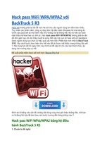
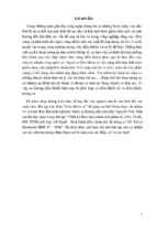
Figure 7-13
A step-by-step illustration of channel
impulse response estimation using a recursive multipath signal
reception filter.
Part 2:
Initial
Shift
register
0
Planning and Designing Data Applications
0
0
0
0
⌺
⌺
⌺
⌺
x(n)
Step 1
Shift
register
3
y(n)
0
0
0
0
⌺
⌺
⌺
⌺
x(n)
Step 2
Shift
register
5
Step 3
6
0
0
0
3
⌺
⌺
⌺
⌺
Step 4
6
0
0
3
2
⌺
⌺
⌺
⌺
Shift
register
6
0
3
2
1
⌺
⌺
⌺
⌺
Shift
register
x(n)
0=6–0–3–2–1
y(n)
3
2
1
0
⌺
⌺
⌺
⌺
x(n)
Step 6
1=6–0–0–3–2
y(n)
x(n)
Step 5
2=5–0–0–0–3
y(n)
x(n)
Shift
register
3=3–0–0–0–0
y(n)
x(n)
Shift
register
0
0=6–3–2–1–0
y(n)
P0
P1
P2
P3
3
2
1
0
⌺
⌺
⌺
⌺
Send the multipath factor to
multipath signal receiver
y(n)
equalization and signal coherent combining are actually implemented
jointly in the proposed scheme under a relatively simple hardware
structure.
3. It operates adaptively to the channel characteristic variation without
needing prior knowledge of the channel, such as interpath delay and
relative strength of different paths. On the contrary, a RAKE receiver
215
Chapter 7: Architecting Wireless Data Mobility Design
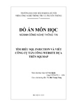
Figure 7-14
The signal detection
procedure of the
recursive multipath
signal reception filter
based on channel
impulse response
estimates with recovered bit stream
y(n) ⫽ (1 ⫺ 1 1 ⫺ 1 1).
0
Initial
x(n)
⌺
Tc
3
Step 1 x(n)
⌺
Step 2 x(n)
Tc
⌺
Step 3 x(n)
⌺
Step 4 x(n)
⌺
Step 5 x(n)
⌺
Step 6 x(n)
Tc
0
–
Tc
0
–
0
Tc
⌺
0
0
Tc
Tc
0
–
–
0
Tc
1/3
–
–
1/3
–
2
–1 = (–1 – 0 – 0 – 2) ⫻ 1/3
sgn()
y(n)
Decision
device
1 = (2 – 0 – 1 + 2) ⫻ 1/3
sgn()
y(n)
Decision
device
–1 = (–2 – 0 + 1 – 2) ⫻ 1/3
sgn()
y(n)
Decision
device
1/3
1 = (2 – 0 – 1 + 2) ⫻ 1/3
sgn()
y(n)
Decision
device
Tc
0
–
–
2
0
1 = (3 – 0 – 0 – 0) ⫻ 1/3
sgn()
y(n)
Decision
device
Tc
0
1
1/3
–
2
⌺
y(n)
Tc
1
⌺
–
–
0
⌺
1/3
–
2
⌺
Decision
device
0
Tc
0
1
⌺
–
0
1
–
0
Tc
–
2
⌺
sgn()
Tc
0
1
⌺
–
0
2
Tc
0
–
2
⌺
–
0
Tc
–
1
⌺
–
0
–2
Tc
0
–
1/3
Tc
0
⌺
–
0
Tc
2
1
⌺
–
0
2
Tc
0
0
0
–1
–
1
⌺
–
⌺
–
0
0
Step 7
⌺
–
1/3
0 = (1 – 0 + 1 – 2) ⫻ 1/3
sgn()
y(n)
Decision
device
Tc
The binary stream is recovered
y(n) = [1 –1 1 –1 1]
216
Part 2:
Planning and Designing Data Applications
in a conventional CDMA system requires the path gain coefficients for
maximal ratio combining, which themselves are usually unknown and
thus have to be estimated by resorting to other complex algorithms.
The performance of the proposed new CDMA architecture with the
recursive filter for multipath signal reception is shown in Figs. 7-15 and
7-16, where two typical scenarios are considered: one for downlink performance and the other for uplink performance, similar to the performance comparison made for the MAI-AWGN channel in Figs. 7-8 and 7-9.3
It is observed from the figures that, in terms of the BER in a synchronous downlink channel, three different codes perform similarly, whereas
in an asynchronous uplink channel, the Gold code and m-sequence performances are much worse than the CC code, because the orthogonality
among both Gold codes and m-sequences is destroyed by asynchronous
bit streams from different mobiles. Nevertheless, the CC-code-based
CDMA system outperforms conventional CDMA systems using either
Gold code or m-sequence by a comfortable margin that can be as large as
4 to 6 dB, because of its superior MAI-independent property.
Bandwidth Efficiency
Previously in this chapter, it was demonstrated that the CDMA architecture based on CC codes and an adaptive recursive multipath signal
reception filter is feasible and performs well. The system offers MAI-free
10–1
M-seq 4-use RAKE
Gold 4-use RAKE
CCC 4-use recursive filter
10–2
BER (for the first user)
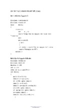
Figure 7-15
Downlink (synchronous) BER for CCcode-based CDMA
and conventional
CDMA systems in a
multipath channel,
with normalized multipath power; interpath delay ⫽ 3 chips;
multipath channel
delay profile ⫽
[1.35,1.08, 0.13];
PG ⫽ 63/64; Gold
code/m-sequence
with MRC-RAKE;
CC-code-based
CDMA with the recursive filter.
10–3
10–4
10–5
0
1
2
3
4
6
5
Eb /N0 (dB)
7
8
9
10
217
Chapter 7: Architecting Wireless Data Mobility Design
10–1
10–2
BER (for the first user)
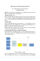
Figure 7-16
Uplink (asynchronous)
BER for CC-code-based
CDMA and conventional CDMA systems
in a multipath channel, with normalized
multipath power;
interpath delay ⫽ 3
chips; interuser delay
⫽ 2 chips; multipath
channel delay profile
⫽ [1.35,1.08, 0.13];
PG ⫽ 63/64; Gold
code/m-sequence
with MRC-RAKE;
CC-code-based CDMA
with the recursive filter.
10–3
10–4
M-seq 4-user use RAKE
Gold 4-user use RAKE
CCC 4-user use recursive filter
10–5
0
1
2
3
4
6
5
7
8
9
Eb /N0 (dB)
10 11 12 13 14 15
operation for both down- and uplink transmissions in an MAI-AWGN
channel. Another interesting property of the new CDMA system is its agility
in changing the data transmission rate, which can be finished on the fly
without needing to stop and search for a code with a specific spreading factor, as required in the W-CDMA standards. Therefore, the rate-matching
algorithm in the proposed system has been greatly simplified.
Yet another important point that has to be addressed is the bandwidth
efficiency of the proposed CDMA architecture. Spreading efficiency in bits
per chip has been used to measure the bandwidth efficiency of a CDMA
system because the bandwidth of a CDMA system is determined by the
chip width of the spreading codes used. Table 7-3 compares the SEs of
three systems: conventional CDMA and CC-code-based CDMA with and
TABLE 7-3
Spreading Efficiency
(in Bits per Chip)
Comparison of
a Conventional
CDMA System and
a CC-Based CDMA
System with and
without Orthogonal
Carriers
PG
8
64
512
4096
32,768
262,144
Conventional CDMA
1/8
1/64
1/512
1/4096
1/32,768
1/262,144
1/8
1/16
1/32
1/64
1/8
1/16
1/32
CC-code-based CDMA
CC-code-based CDMA
(orthogonal carriers)
1
218
Part 2:
Planning and Designing Data Applications
without orthogonal carriers.3 It is clear that the CC-code-based CDMA
systems have a much higher SE figure than a conventional CDMA does,
especially when the processing gain is relatively high.
However, there exist some technical limitations for the proposed CCcode-based CDMA system, which ought to be properly addressed and can
become the direction of possible future work for further improvement.
Obviously, a CC-code-based CDMA system needs a multilevel digital
modulation scheme to send its baseband information, because of the use
of an offset-stacked spreading modulation technique, as shown in Figs. 7-6
and 7-7. If a long CC code is employed in the proposed CDMA system,
the number of different levels generated from a baseband spreading
modulator can be a problem. For instance, if the CC code of L ⫽ 4 is
used, as shown in Table 7-2, five possible levels will be generated from
the offset-stacked spreading: 0, ⫺2, and ⫺4. However, if the CC code of
L ⫽ 16 in Table 7-2 is involved, the possible levels generated from the
spreading modulator become 0, ⫺2, ⫺4, …, ⫺16, comprising 17 different
levels. In general, the modulator will yield L ⫹ 1 different levels for a
CC-code-based CDMA system using length L element codes. Given the
element code length (L) of the CC code, it is necessary to choose a digital
modem capable of transmitting L ⫹ 1 different levels in a symbol duration. An L ⫹ 1 quadrature amplitude-modulated (QAM) digital modem
can be a suitable choice for its robustness in detection efficiency. It
should be pointed out that the simulation study concerned in this part of
the chapter assumes an ideal modulation and demodulation process.
Thus, the research takes into account the nonideal effect of multilevel
carrier modulation, and demodulation remains a topic of future study.
Finally, another concern with the CC-code-based CDMA system is
that a relatively small number of users can be supported by a family of
the CC codes. Take the L ⫽ 64 CC code family as an example. It is seen
from Table 7-3 that such a family has only eight flocks of codes, each of
which can be assigned to one channel (for either pilot or data). If more
users should be supported, long CC codes have to be used. On the other
hand, the maximum length of the CC codes is in fact limited by the maximal number of different baseband signal levels manageable in a digital
modem, as mentioned earlier in this chapter. One possible solution to
this problem is to introduce frequency divisions on top of the code divisions in each frequency band to create more transmission channels.
Conclusion
In this chapter, a new CDMA architecture based on CC codes was presented, and its performance in both MAI-AWGN and multipath channels
was evaluated by simulation. The proposed system possesses several
Chapter 7: Architecting Wireless Data Mobility Design
219
advantages over conventional CDMA systems currently available in 2G
and 3G standards:
1. The system offers much higher bandwidth efficiency than is achievable in conventional CDMA systems. The system, under the same
processing gain, can convey as much as 1 bit of information in each
chip width, giving a spreading efficiency equal to 1.
2. It offers MAI-free operation in both synchronous and asynchronous
MAI-AWGN channels, which attributes to cochannel interference
reduction and capacity increase in a mobile cellular system. This
excellent property also helps to improve the system performance in
multipath channels, as shown by the obtained results.
3. The proposed system is inherently capable of delivering
multirate/multimedia transmissions because of its offset-stacked
spreading modulation technique. Rate matching in the new CDMA
system becomes very easy, just shifting more or fewer chips between
2 consecutive bits to slow down or speed up the data rate—no more
complex rate-matching algorithms.
This chapter also proposed a novel recursive filter, particularly for
multipath signal reception in the new CDMA system. The recursive filter consists of two modules working jointly; one performing channel
impulse response estimation and the other detecting signal contaminated
by multipath interference. The recursive filter has a relatively simple
hardware compared to a RAKE receiver in a conventional CDMA system, and performs very well in multipath channels. The chapter also
addressed technical limitations of the new CDMA architecture, such as
a relatively small family of CC codes and the need for complex multilevel digital modems. Nevertheless, the proposed CDMA architecture
based on complete complementary codes offers a new option to implement future wideband mobile communications beyond 3G.
The increasing amount of roaming data users and broadband Internet
services has created a strong demand for public high-speed IP access
with sufficient roaming capability. Wireless data LAN systems offer high
bandwidth but only modest IP roaming capability and global user management features.
This chapter described a system that efficiently integrates wireless
data LAN access with the widely deployed GSM/GPRS roaming infrastructure. The designed architecture exploits GSM authentication, SIMbased user management, and billing mechanisms and combines them
with public WDLAN access.
With the presented solution, cellular operators can rapidly enter the
growing broadband access market and utilize their existing subscriber
management and roaming agreements. The OWDLAN system allows
220
Part 2:
Planning and Designing Data Applications
cellular subscribers to use the same SIM and user identity for WDLAN
access. This gives the cellular operator a major competitive advantage
over ISP operators, who have neither a large mobile customer base nor a
cellular kind of roaming service.
Finally, the designed architecture combines cellular authentication
with native IP access. This can be considered the first step toward all-IP
networks. The system proposes no changes to existing cellular network
elements, which minimizes the standardization effort and enables rapid
deployment. The reference system has been commercially implemented
and successfully piloted by several mobile operators. The GSM SIMbased WDLAN authentication and accounting signaling has proved to
be a robust and scalable approach that offers a very attractive opportunity for mobile operators to extend their mobility services to also cover
indoor wireless data broadband access.
References
1. “Wireless Architecture Options,” Synchrologic, 200 North Point Center
East, Suite 600, Alpharetta, GA 30022, 2002.
2. “CIO Outlook 2001: Architecting Mobility,” Synchrologic, 200 North
Point Center East, Suite 600, Alpharetta, GA 30022, 2002.
3. Hsiao-Hwa Chen, Jun-Feng Yeh, and Naoki Suehiro, “A Multicarrier
CDMA Architecture Based on Orthogonal Complementary Codes for
New Generations of Wideband Wireless Communications,” IEEE Communications Magazine, 445 Hoes Lane, Piscataway, NJ 08855, 2002.
4. John R. Vacca, The Essential Guide to Storage Area Networks, Prentice
Hall, 2002.
8
Fixed Wireless Data
CHAPTER
Network Design
Copyright 2003 by The McGraw-Hill Companies, Inc. Click Here for Terms of Use.
222
Part 2:
Planning and Designing Data Applications
If you can’t wait for DSL or cable modem3 to be installed at your corporate headquarters or if it seems like broadband4 will never be available
at your remote sites, the design of a fixed wireless data network is
becoming a viable alternative for last-mile Internet access.
Fixed wireless data has some advantages over wired broadband: It
can be installed in a matter of days. Once the line of sight is established,
the connection isn’t susceptible to the types of weather-related or accidental outages that can occur with wired networks.
But there are important design issues that network executives will
need to resolve before signing up for fixed wireless data, including security and possible performance degradation from interference with other
service providers.
For example, on the island of Anguilla, a British territory 6 miles north
of St. Martin in the Caribbean, Weblinks Limited (http://www.weblinksadvertising.co.uk/contact_frameset.html) has installed a wireless data Internet system that covers the entire 16-mile-long island, offering services to a
growing number of e-commerce6 companies. On a hurricane-prone and
remote island like Anguilla, fixed wireless data offers several benefits over
DSL and cable modem. A fixed wireless Internet system, such as Weblinks’
in Anguilla, consists of centralized transceiver towers and directional
antennas mounted at each end-user location to maximize range and minimize the number of towers needed to cover a large area (see sidebar, “Wireless Data Internet Infrastructure”). (The Glossary defines many technical
terms, abbreviations, and acronyms used in the book.)
Wireless Data Internet Infrastructure
Independent service providers are building private networks based
on a combination of optical and fixed wireless data technology,
exclusive peering arrangements, and Internet data centers to support the B2B marketplace. The arrival of the twenty-first century
in Latin America coincided with the migration of the region’s Internet from a communications/recreation medium to a platform for
mission-critical applications and e-business. With this change, the
region’s Internet infrastructure is evolving from its dependence on
U.S.-based hosting facilities and incumbent owned and operated
transport to a mix of fiber-optic and fixed wireless data private networks with Internet data centers (IDCs).
Until a few years ago, the dot-coms that pioneered Latin American Web content looked to local garages or U.S.-based Web-hosting
firms for their infrastructure needs, since high-quality solutions
did not yet exist in the region. The distance between U.S. hosting
Chapter 8: Fixed Wireless Data Network Design
223
facilities and Latin American users, combined with subpar infrastructure tying the two regions, resulted in poor performance and
high-latency connections. Such concerns were not critical, however,
because of the informational nature of the first Web sites. The
ready-made U.S. solutions, which transported international traffic
over satellite networks 5 or directed in-region traffic “hot-potato”
style through multiple hubs and network access points (NAPs),
suited both providers and users.
Even today, many connections throughout the region suffer
delay as a result of poor routing. For example, a user in Buenos
Aires accessing a site hosted in California connects to an Internet
service provider (ISP) that in turn connects to an Internet backbone provider. Upon leaving the ISP network, the connection travels across the Internet “cloud.” The network providers inside the
cloud have no incentive or ability to optimally route the connection.
Their motivation is to minimize the costs by routing across inexpensive and usually overly utilized links or by passing the session
off to another less expensive and lower-quality network as soon as
possible. This process, known as hot-potato routing, increases the
number of hops and degrades the quality of the session.
If a user connects to a local ISP in Argentina or Brazil to access
content that is hosted in the same city or country, the user’s traffic
is often routed to the United States, where it will be redirected at a
public NAP back to its destination in South America. That occurs
because of the limited partnerships at public access points and lack
of peering agreements between local providers.
The ISP’s backbone provider is likely an incumbent telecommunications provider with a legacy voice-based network. The legacy
network’s routers and links can add significant latency and packet
loss to the session. The provider’s network is also likely to include
single points of failure that pose the risk of session failure.
The precise number of hops, amount of packet loss, and amount of
latency varies with each session and the network topologies of the
connection. Generally, packets passing from sites in the United
States to Buenos Aires would generate 500 ms or more of round-trip
latency. Compounded by multiple packets making up a Web page,
such latency can produce 8 s or more delay in page downloads.
Today’s Pan-Regional Internet Backbone
The Internet is entering the second phase of its evolution in Latin
America. By 2000, the region emerged as the fastest-growing Internet market in the world. Companies no longer use the Web merely
to market their products and services; many are developing highly
224
Part 2:
Planning and Designing Data Applications
complex, transaction-enabled sites. Market researcher International Data Corporation foresees e-commerce in the region growing to
more than $9 billion by 2004. Merrill Lynch predicts the Web hosting market in Latin America will reach $2.4 billion in revenue by
2006.
In light of this e-commerce growth, it is clear solutions presented
by foreign hosting firms via satellite transmissions and public NAP
routing no longer meet the needs of the region’s businesses. This situation is opening the door for ISPs to build private networks and
IDCs in the region. Today, the local hosting sector is meeting these
new demands through an optical backbone that enables quality of
service, private peering relationships, content distribution, and managed hosting.
Problems posed by hot-potato routing and NAP bottlenecks
resulted in insufficient transport for the mission-critical applications of the second phase of the Latin American Internet. The reliability and performance of each connection were greatly affected by
the logical proximity and network availability of the links. Furthermore, much of the international traffic was transmitted via satellite
connections, which are expensive and lack scalability. Other options
existed, like submarine cables, but these were primarily consortium
ventures controlled by incumbent carriers and were voice-centric
in nature.
As a result of these challenges, a huge demand for data-centric
traffic capacity grew in the region. And the increasing concerns for
the latency and packet-loss issues posed by satellites drove several
global network providers, including 360networks, Emergia, and
Global Crossing to build their own fiber-optic connections within
the region, connecting to the United States and other international
fiber networks. These new fiber cables have enabled new entrants
in Latin America to construct pan-regional fiber backbones.
Through an international fiber-optic backbone, carriers found a
highly scalable solution that allowed them to add customers quickly
and cost-effectively. A provider or customer can now get an STM-1
(155-Mbps) connection with 10 times the capacity on a fiber network
for the same cost as 15 Mbps of satellite capacity a year ago. But, the
customer value of these new backbones comes through the control
new providers are able to guarantee through private peering
arrangements at IDCs and content delivery features that better
manage the flow of traffic around the globe.
As a result of the growth in number of local hosting facilities and
improved intracountry networks, about 50 percent of the traffic in
Chapter 8: Fixed Wireless Data Network Design
225
Brazil today stays local instead of traveling over pan-regional or
international networks before reaching its destination. The physical proximity also assists companies with some of the psychological
challenges of transitioning mission-critical applications to the Web.
The ability to touch and see Web hardware provides reassurance to
organizations that are moving highly important information on
line. However, there is a reluctance to outsource mission-critical
applications remotely as a major attraction for local hosting. A local
solution allows the company to bring a potential client to see first
hand the secure location of a hosting platform.
The physical proximity to the Latin American user base can also
help with necessary local dedicated links. Many application serviceprovider designs, for instance, call for dedicated local loops between
the IDC and offices with high user concentrations. While such links
would be prohibitively expensive from the United States, they become
affordable when run from a local location.
In this scenario, when the Buenos Aires user requests content,
located, for example, in a Miami or Mexico IDC, the request travels
through the user’s ISP to a private optical network. The opticalnetwork provider’s routers then broadcast the requested IP address
because the content is hosted on the same pan-regional network (see
Fig. 8-1).1 The fiber-optic infrastructure provides a fast, reliable connection to the content located in the Miami or Mexico IDC.
The optimal solution is for a hosting provider to operate an optical network with multiple paths and access points in each of its
markets. Any traffic that enters the provider’s network is quickly
moved over private connections to the server. In this scenario, any
user located near an access point can access any Web server anywhere on the network at the same high speed.
The hosting provider’s pan-regional presence can be utilized to
provide a distributed architecture for Web content as well, using
technologies such as shared caching, dedicated caching, and server
mirroring. This array of choices provides for a wider range of distributable content, including applications and secure content.1
Security Concerns
Another key issue with wireless data Internet is security. A poorly
secured system lets eavesdroppers access sensitive information.
If you plan to transmit credit card numbers, Social Security numbers,
and passwords over a wireless data network, then you’d better be sure
226
Server
Internet cloud
ISP – Internet service provider
– Router
Internet
user
Internet
user
ISP
Buenos Aires, Argentina
ISP
Data
Diveo network
Server
ISP
Buenos Aires, Argentina
(b)
Figure 8-1 Map (a) illustrates the traditional hot-potato routing of Internet traffic,
while map (b) shows the routing of Internet traffic over private optical networks with
Internet data centers.
Data
(a)
Evolution to private networks
Chapter 8: Fixed Wireless Data Network Design
227
the system supports adequate security mechanisms. The IEEE 802.11
wired equivalent privacy (WEP) might not be good enough.
Researchers at the University of California at Berkeley have found
flaws in the 802.11 WEP algorithm and claim it is not capable of providing adequate security. A problem with the 802.11 WEP is that it requires
the use of a common key throughout the network for encrypting and
decrypting data, and changing the keys is difficult to manage. This
makes the system vulnerable to breaches in security, and network executives should be cautious when implementing 802.11 networks.
Network executives should ensure that wireless data service providers
implement enhanced security beyond 802.11 WEP (such as IEEE 802.1x).
Some vendors, such as Cisco,7 implement security mechanisms that utilize a different key for each end user and automatically change the key
often for each session. This greatly enhances information security.
Finally, let’s look at an overview of a fixed low-frequency broadband
wireless data access system for point-to-multipoint voice and data applications. Operating frequency bands are from 2 to 11 GHz, and the base
station can use multiple sectors and will be capable of supporting smart
antenna technology. The product system requirements, design of the
radio subsystem specification, and an analysis of microwave transmission related to current radio technologies are presented. Examples of
BWDA technology are provided.
Fixed Broadband Wireless Data
Radio Systems
Global integration and fast-growing business activity in conjunction
with remote multisite operations have increased the need for high-speed
information exchange. In many places around the world, the existing
infrastructure is not able to cope with such demand for high-speed communications. Wireless data systems, with their fast deployment, have
proven to be reliable transmission media at very reasonable costs. Fixed
broadband wireless data access (BWDA) is a communication system
that provides digital two-way voice, data, Internet, and video services,
making use of a point-to-multipoint topology. The BWDA low-frequency
radio systems addressed in this part of the chapter are in the 3.5- and
10.5-GHz frequency bands. The BWDA market targets wireless data
multimedia services to small offices/home offices (SOHOs), small and
medium-sized businesses, and residences. Currently, licensed bands for
3.5-GHz BWDA systems are available in South America, Asia, Europe,
and Canada. The 10.5-GHz band is used in Central and South America
228
Part 2:
Planning and Designing Data Applications
as well as Asia, where expanding business development is occurring. The
fixed wireless data market for broadband megabit-per-second transmission rates, in the form of an easily deployable low-cost solution, is growing
faster than that for existing cable and digital subscriber line (xDSL) technologies for dense and suburban environments.
This part of the chapter also describes the BWDA network system, the
radio architecture, and the BWDA planning and deployment issues for 3.5and 10.5-GHz systems. Table 8-1 summarizes the system characteristics for
each frequency range according to various International Telecommunication Union—Radiocommunication Standardization Sector (ITU-R) drafts,
EN 301 021, IEEE 802.16, and other national regulations.2 A maximum of
35 Mbps capacity is achievable for 64 quadrature amplitude modulation
(QAM) over 7-MHz channel bandwidth. Coverage ranges for line-of-sight
links are given for 99.99 percent availability.
The BWDA System Network
A BWDA system comprises at least one base station (BS) and one or more
subscriber remote stations (RSs). The BS and RS consist of an outdoor
unit (ODU), which includes the radio transceiver and antenna, and an
indoor unit (IDU) for modem, communication, and network management
(see Fig. 8-2).2 The two units interface at an intermediate frequency (IF);
optionally, the RS ODU and IDU can be integrated. The BS assigns the
radio channel to each RS independently, according to the policies of the
media access control (MAC) air interface. Time in the upstream channel
is usually slotted, providing for time-division multiple access (TDMA),
whereas on the downstream channel, a continuous time-division multiplexing (TDM) scheme is used. Each RS can deliver voice and data using
TABLE 8-1
The 3.5- and
10.5-GHz System
Characteristics
Product
3.5 GHz
10.5 GHz
Frequency, GHz
3.4–3.6
10.15–10.65
Tx/Rx spacing, MHz
100
350
Channelization, MHz
3.5, 5, 7
3.5, 7
RS upstream modulation
QPSK/16 QAM
QPSK
RS downstream modulation
16/64 QAM
16 QAM
RS upstream capacity, Mbps
5–20
5, 10
RS downstream capacity, Mbps
12–34
12, 23
Coverage radius, km
19
8
229
Edge router
Figure 8-2
PSTN
V5.2/GR.303
PSTN
gateway
STM-1/OC-3c
STM-1/OC-3c
Router and
concentrator
Radio tower
Base station
TDMA/TDM
FDD
3.5 GHz
10.5 GHz
Air interface
Fixed broadband wireless data access system architecture.
CLEC
ATM network
Internet
Network management
and billing system
IDU modem
ODU radio
Remote station
E1/T1 clear channel
E1/T1
V.35N ⫻ 64
POTS
10/100 Base-T
PBX
Video
LAN
230
Part 2:
Planning and Designing Data Applications
common interfaces, such as plain old telephone service (POTS), Ethernet,
video, and E1/T1. Depending on the type of service required by the client,
remote stations can provide access to a 10/100Base-T local-area network
(LAN) for data access and voice over IP (VoIP) services to (1) a LAN and
up to eight POTS units for small businesses or (2) a LAN and an E1/T1
channel connected to a private branch exchange (PBX) for small and medium enterprises.
The BS grooms the voice and data channels of several carriers and provides connection to a backbone network (IP or asynchronous transfer
mode, ATM) or transport equipment via the STM1/OC-3c (155.52 Mbps)
high-capacity fiber link. The ATM network gives access to the public
switched telephone network (PSTN) gateway through competitive local
exchange carriers (CLECs) using V5.2/GR.303 standards, or to an edge
router for accessing the Internet data network through Internet service
providers (ISPs). The ATM network interface is also connected to the network management system via Simple Network Management Protocol
(SNMP) for performing tasks such as statistics and billing, database control, network setup, and signaling alarms for radio failures. Configuration
of the radio network link is made possible through a Web browser http
link via TCP/IP.
Each BS has a certain available bandwidth per carrier that can be
fully or partially allocated to a single RS either for a certain period of
time [variable bit rate (VBR) or best effort] or permanently [constant
bit rate (CBR)]. BWDA systems are envisioned to work with a TDMA
rather than a code-division multiple-access (CDMA) scheme in order
to counteract propagation issues. Also, for non-line-of-sight (NLOS)
environments, BWDA systems with a single carrier with frequency
domain equalizer and decision feedback equalizer (FD-DFE) or orthogonal frequency-division multiplexing (OFDM) technologies are applicable. Small and medium-size businesses require fast and dynamic
capacity allocation for data and voice packet-switched traffic. This
TDMA access scheme can be applied to either frequency-division
duplexing (FDD) or time-division duplexing (TDD). Both duplexing
schemes have intrinsic advantages and disadvantages, so the optimum
scheme to be applied depends on deployment-specific characteristics
(bandwidth availability, Tx-to-Rx spacing, frequency congestion, and
traffic usage). Targeting the business market, for example, are Harris
ClearBurst MB (http://www.harris.com/harris/whats_new/pacnet.html)
products, which are designed for FDD. In symmetric two-way data
traffic, FDD allows continuous downstream and upstream traffic on
both low- and high-band channels. Moreover, it has full flexibility for
instantaneous capacity allocation, dynamically set through the MAC
channel assignment.
231
Chapter 8: Fixed Wireless Data Network Design
The Radio-Frequency System
RF subsystems consist of the base station and remote station ODUs. This
part of the chapter will provide a global understanding of the different RF
technologies employed for high-performance low-cost radio design. In
addition to meeting all the functional, performance, regulatory, mechanical, and environmental requirements, the radio system must achieve most
of the following criteria:
Cost-effectiveness
Maintenance-free
Easily upgradable
Quick installation
Attractive appearance
Flexibility
Scalability2
An example of a BWDA radio system is shown in Fig. 8-3: a base station ODU, part of the ClearBurst MB product.2 Its radio enclosure contains two sets of identical transceivers with high-power amplifiers and RF
diplexers for redundancy. A dual flat-panel antenna is directly integrated
with the enclosure. A single coaxial cable is used to connect to the indoor
base station router unit. The base station radio units can be mounted on
Pole mounting
Figure 8-3
The Harris base station
outdoor radio unit.
BS radio
enclosure
Dual
antenna
Coax cable to
IDU router
232
Part 2:
Planning and Designing Data Applications
a pole, a tower, or a wall. The remote station ODU is an unprotected unit,
where a single transceiver with a medium-power amplifier is used. The
enclosure is directly connected to the flat-panel antenna. In addition, an
alignment indication connector is also provided for antenna installation
and alignment with the base station.
An ODU radio consists of transmitter and receiver circuits, frequency
sources, a diplexer connected to the antenna, and a cable interface to connect to the indoor modem unit. Moreover, a minimum of “intelligence” is
required in the radio to control the power level throughout the transceiver.
Development of software-controlled radios is presently underway, but the
issue of cost-effectiveness remains. Typically, for small businesses or residential markets, cost is the main factor that comes into play; hence, a design
made simpler by limiting radio intelligence may translate into less demanding requirements for the radio processor. Software-controlled radios present many advantages, such as reducing hardware complexity, but it is up
to the design engineers to compromise among the high performance, low
cost, and flexibility of the product.
A low-cost, low-performance radio solution appropriate for the highvolume residential market is shown in Fig. 8-4 as a “dumb” transceiver.2
This architecture uses a minimal number of hardware components, integrated with or without software control capabilities. Following the RF
diplexer, the receive (Rx) path includes a low-noise amplifier, bandpass filters (BPFs) for image-reject and channel-select filtering, a downconverter
mixer, and an open loop gain to allow a wide input dynamic range. The
transmitter (Tx) consists mainly of an upconverter associated with
some filtering and a power amplifier (PA). The local oscillator (LO) may
provide for fixed or variable frequency to the mixers. A fixed LO would
give a variable IF; hence, by using a wider BPF bandwidth, the receiver
would not be immune to interference. Adding a microcontroller to the
radio provides control of the phase-locked loop (PLL) for the transceiver
synthesizer and can put the PA into mute mode. Single up/downconversion
stages further reduce the overall cost, but at the expense of lower radio
performance. Two separate IF cables simplify the interfacing.
LNA
Figure 8-4
A dumb transceiver:
block diagram.
BPF
MXR
BPF
AGC
RF in
Diplexer
RF out
Rx IF out
LO
PA
BPF
MXR
BPF
Tx IF in
ATT
233
Chapter 8: Fixed Wireless Data Network Design
An intelligent transceiver involves more digital and software-controlled
circuitry, and hence higher cost. Figure 8-5 shows a transceiver block diagram which includes closed-loop gain control, cable, and fade margin
compensation on the transmit and receive paths, that is, power detection
circuits on Rx IF, Tx chain, and PA.2 The transmitter mutes on a synthesizer out-of-lock alarm in order to avoid transmitting undesirable frequencies, and also on no received signal. The microcontroller provides for the
receive signal strength indicator (RSSI) level for antenna alignment, and
for control and monitor channels. A single cable is used for all input
and output IFs, the telemetry signal, and the dc biasing from the IDU.
Software control also allows for calibrated radios, which results in no gain
variation or frequency shifting of the signal with respect to temperature
variation. Technology advancement in the past few years in the RF integrated circuit market allows for greater chip integration using commercial off-the-shelf (COTS) devices and simplified hardware board-level
design. This architecture achieves better performance, especially for highermodulation schemes, and therefore is suitable for higher-capacity radios
targeting the business market.
The modulation scheme chosen for the radio system depends on several
product definition factors, such as required channel size, upstream and
downstream data rates, transmit output power, minimum carrier-to-noise
ratio (C/N), system availability, and coverage. Table 8-2 gives the characteristics for quadrature phase-shift keying (QPSK) and QAM signals typically used for BWDA systems for 7-MHz channel bandwidth.2
A system can require symmetric or asymmetric capacity, depending on
its specific application. For a symmetric capacity system, upstream and
downstream traffic are equivalent, whereas for an asymmetric system,
the downstream link usually requires more capacity. Hence, higher-level
modulations with higher capacity are better suited to downstream transmissions. Using n QAM modulations for downstream transmission
becomes advantageous, whereas QPSK can be used in the upstream
Figure 8-5
An intelligent
transceiver: block
diagram.
RF in
LNA
BPF
MXR
BPF AMP MXR BPF
VAR
ATT
AMP
Power
detector
Rx synthesizer
Microcontroller
microprocessor
Diplexer
Rx/Tx
synthesizer
DC
Memory A/D
Power
detector
RF out
IF out
Cable
interface
Alarm
Tx synthesizer
IF in
PA AMP BPF MXR
AMP BPF MXR
AMP
ATT
RSSI
MAC
modem
- Xem thêm -