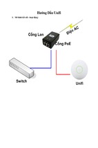
Cấu hình Master Clock GPS
1
Masterclock MCR5000 User Manual – Original – Sept 2012
Table of Contents
The MCR5000 is a high‐precision time and
frequency reference system based on
NTP (Network Time Protocol) over the
Ethernet. Designed for the rack mount,
this multiple input and output generator
serves commercial establishments,
industry, military and laboratory
environments. GPS, NMEA and Time Code
options are available.
Thank you for your purchase of a
MCR5000 precision time and frequency
reference system from Masterclock.
Here you’ll find instructions for
unpacking and installing your MCR5000,
proper care and configuration.
We are here to help. You can reach us
using various contact methods (phone,
email, etc.) found at our website:
www.masterclock.com
Before calling, please attempt to find the
answer to your situation here. You’ll find
this user manual will handle virtually all of
your questions.
DISCLAIMER The information contained
in this document is subject to change
without notice. Masterclock®, Inc.
(hereinafter Masterclock or MC) makes
no warranty of any kind with regard to
this material, including, but not limited
to, the implied warranties of
merchantability and fitness for a
particular purpose. Masterclock shall not
be liable for errors contained herein or
for incidental or consequential damages
in connection with the furnishing,
performance, or use of this material. See
important limited warranty information
starting on page 10.
Introduction, Driver Installation .............................................. 4
Standard Features .................................................................. 5
Password Protection, Time Zones ........................................... 6
DHCP/BootP Auto Configuration ............................................. 8
Device Naming ....................................................................... 9
NTP Client ............................................................................ 10
Memory and Factory Defaults ................................................ 10
Optional Features ................................................................. 12
Back Panel Interfaces ............................................................ 14
Installation .......................................................................... 16
R‐232 Communications ......................................................... 17
WinDiscovery Installation and Operation .............................. 19
How to Listen for NTP ........................................................... 32
Using Telnet ......................................................................... 34
Time Code Generation Option .............................................. 35
GPS Option ........................................................................... 36
Additional NEMA 0183 Sentence Outputs ............................. 39
"Soft"Restarts ...................................................................... 42
Troubleshooting Tips ............................................................ 43
Specs ..................................................................................... 51
Limited Warranty and Service ................................................ 56
Certificate of Conformity ...................................................... 57
Contact Information .............................................................. 58
Masterclock MCR5000 User Manual – Original – Sept 2012
2
OPERATING ENVIRONMENT
Moisture: The MCR5000 is not moisture‐proof. It is designed for
indoor use only. Treat it as you would any other delicate
electronic device and do not expose it to water, high humidity
excessive heat or physical abuse. Please see the “Specifications”
section (p. 48) for details.
Static: Do not subject the unit, particularly the antenna input
connector, to electrostatic discharge (ESD) during handling.
Discharge yourself to a ground before handling the unit.
Preferably, use a static discharge wrist strap connected to earth
ground when installing or configuring the device.
Caution: No user‐serviceable parts are inside the MCR5000.
Please contact the factory if you require service or repair
3
Masterclock MCR5000 User Manual – Original – Sept 2012
Introduction
When locked to GPS satellites, the MCR5000 can read NTP,
NMEA, NENA or time can be set manually. The MCR5000 can
generate NMEA, NENA, PPS or PC time via USB.
Optional outputs include NTP, Time Code basic (IRIG B and
SMPTE), Time Code Advanced (IRIG A and E), PPO and a 10
MHz sine wave.
SEE THE PRE‐INSTALLATION
CHECKLIST AND QUICK START
INSTRUCTIONS: PAGE 18
QUICK DRIVER INSTALLATION
1. Insert the USB cables and
configuration software CD that
shipped with your MCR5000.
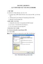
2. Onscreen select the MCR5000
directory.
3. Run the ‘setup.exe’ application
from the CD.
By default, the setup utility will
suggest installing files to C:\Program
Files\ Masterclock\MCR5000.
4. Click [Okay].
Open the software by clicking the
shortcut in your start menu.
Note: Other methods should not be
used to manage the device while using
this software.
Holdover accuracy and stability is maintained with a High
Stability Oven‐controlled Oscillator (HSO). Each MCR5000 can
operate on a 10/100 MBit local area network.
DRIVER INSTALLATION
The MCR 5000 is available in multiple configurations to fit
almost any need with configurable plug‐in modules.
A USB type B port has been included on the rear of the
MCR5000 to provide a means of configuring the operation of
the MCR5000 via software or as a serial data port.
To utilize the USB port with a host computer, connect a USB
type A/B cable from the host computer to the MCR5000.
Before the unit can be configured, the device drivers must
first be loaded. A software configuration program
(WinDiscovery) and USB drivers have been provided on a CD
with the MCR5000.
Installing USB drivers: Once the MCR5000 is powered up, the
Windows Plug and Play Manager will detect the new
Masterclock USB device and request drivers. Insert the driver
software CD into the CD reader of your computer.
When requested by the Windows Plug and Play Manager,
select the option to “Install from a list or specific location
[Advanced]” in order to manually browse for the drivers.
Browse to the drivers located under the Drivers\MCR\
directory on the CD and select [OK], then select [Next].
The driver will automatically load into your computer. If not,
see the box at left for other instructions.
FRONT PANEL ‘LED’ STATUS
The MCR5000 provides two LEDs on the front panel.
The upper amber LED (labeled: Activity) pulses briefly and
only occasionally with every NTP request.
The lower green LED (labeled: Reference Lock) blinks twice
per second during power up, then once per second after
synching to the external reference.
Masterclock MCR5000 User Manual – Original – Sept 2012
4
WINDISCOVERY
Included with your MCR5000 is the WinDiscovery GUI
application. WinDiscovery is a detection, configuration, &
management software application which works with all
Masterclock brand network devices. It operates under the
Windows XP/7, Server 2003 2008 operating systems.
FRONT PANEL LED DISPLAY OPTIONS
•
Six‐digit time or date or alternating time/date display
•
Two‐window, twelve‐digit date and time display
•
12‐ or 24‐hour time
•
Display in either US [MMDDYY]
or European [DDMMYY] formats
•
Adjustable brightness control
•
Display UTC time or local time with fully configurable
time zone and DST offsets
BATTERY BACKED RTC AND TCXO
The MCR5000 maintains its internal time settings in battery‐
backed memory located on a RTC chip. A Temperature
Compensated Crystal Oscillator (TCXO) provides a
freewheeling accuracy (maximum drift) of +/‐ 1 minute per
year (165 mS/day).
The battery supplies power to the TCXO 32kHz oscillator and
RTC when the unit is powered off. This allows the internal
time to be maintained and the time and date to increment,
when power is off. Under normal operating condition, the
memory devices maintaining the RTC data is powered by the
external DC power supply and does not rely on the battery for
data retention.
The battery is a maintenance‐free rechargeable manganese
lithium type. A built‐in battery charging circuit is used when
the unit is powered on, eliminating the need for
maintenance.
Masterclock MCR5000 User Manual – Original – Sept 2012
5
NON‐VOLATILE MEMORY CONFIGURATION
The MCR5000 maintains its configuration parameters
internally in non‐volatile memory, even when the power is
off. These configuration settings include the assigned (DHCP
or Static) IP address and network settings, assigned device
name, NTP operational mode, brightness level, assigned
stratum levels, Telnet access, RTC usage validity during
primary reference outages and password. All configuration
parameters (except for the time/date stored in the RTC) may
be reset to the factory default state (see below).
SET TO FACTORY‐DEFAULT CONFIGURATION
The MCR5000 is fully tested with factory defaults prior to
shipping. This factory default configuration is defined as:
•
UTC reference time (no local time zone offset, daylight
saving auto adjustment disabled)
•
DHCP configuration mode enabled for Network Address
and NTP Server addresses
•
Query (unicast) NTP client mode enabled (broadcast/
multicast modes disabled)
•
Time dissemination via Real‐Time Clock (RTC) during
reference outages enabled for 24 hours
•
Password – set to “public”
•
Device name – set to MCR1000‐XX:XX
(where XX:XX are the last two octets
of the MAC address of the unit)
•
Relay Schedule – disabled (relay actuates
upon loss of external time reference)
•
Telnet enabled
RESET TO FACTORY DEFAULTS
SET TO FACTORY DEFAULT BUTTON ACCESS
HOLE To reset the configuration back to the
factory default insert the end of a paperclip
into the pinhole marked here. Push in to
depress the “Set to factory default” button
inside the unit. Maintain pressure for 5
seconds or until the front panel display goes
to all dashes “‐ ‐ ‐ ‐ ‐ ‐ “.
In some situations (such as a lost password or removal of
confidential information, perhaps prior to sending the unit in
for repair service), it may be necessary to return the
MCR1000 to its factory default configuration. The factory
defaults may be restored by using the software interface
method (WinDiscovery or Telnet) or by accessing a recessed
button located on the front panel (see illustration at left) in
recessed pinhole. Insert a paperclip‐type wire into the hole
and maintain pressure for at least 5 seconds.
Masterclock MCR5000 User Manual – Original – Sept 2012
6
Standard Features
TIME CODE INPUT NOTICE
Depending on many factors beyond the
control of MC, the signals that are
received from the Time Code Input
Source are subject to interference, noise,
loading effects and other influences such
as time code format that could cause the
MCR5000 with an installed TCR (Time
Code Reader) option to provide
erroneous time and/or date information
and, under some conditions, could
prevent it from providing time/date
information.
•
Internal battery‐backed Real Time Clock (RTC) retains
time during loss of power or loss of active reference(s).
•
Maintenance‐free rechargeable battery
•
Additional Telnet interface for alternate configuration
and maintenance on non‐Windows OS networks
•
Temperature Compensated Oscillator (TCXO)
with holdover stability <165mS/day
•
Supports NTP broadcast, multicast and/or unicast
(query) modes
•
Fully configurable network settings, automatic via
DHCP/BOOTP, or Static IP addressing support
•
Security features include password protection of
configuration, authenticated communications and the
ability to disable Telnet management access
•
UTC time internal reference
TIME CODE OUTPUT NOTICE
Depending on many factors beyond the
control of MC, the time code signals that
are generated from the MCR5000 with an
installed TCG (time code generator)
option are subject to interference, noise,
loading effects and other influences, such
as a time code format that could affect a
device decoding the time code signal to
provide erroneous time and/or date
information. The time code output of this
device should not be relied upon for
critical timing applications.
•
Fully configurable local time offset support with Time
Zone and Daylight Saving Time (DST) offset, along with
the ability to create custom time offsets
•
Remotely monitor status and behavior via easy‐to‐use
WinDiscovery software
•
Single event (daily) programmable relay schedule
(upgradeable to multi‐event with Event Time software)
•
PPS (Pulse Per Second) output TTL level signal which is
locked to the most accurate active time reference
•
Front panel power and NTP activity LED status indicators
• Programmable Dry Contact Relay (24VDC or 24VAC,
250mA) for scheduled events
GPS RECEIVER NOTICE
Depending on many factors beyond the
control of Masterclock, the signals that
are received from the GPS satellites are
subject to interference, fading, satellite
failure and other influences that could
cause the MCR5000 with an installed GPS
receiver option to provide erroneous time
and/or date information and, under some
conditions, could prevent it from
providing time/date information.
It is the responsibility of the user to
determine the adequacy and suitability
of this device for the intended use.
• USB serial port interface
•
RS232 serial port Interface
• NMEA 0183 ASCII serial output
•
Kinemetrics/Truetime
•
NENA 911 PSAP master clock standard
• Firmware and function upgradeability
Masterclock MCR5000 User Manual – Original – Sept 2012
7
Optional Features
While the MCR5000 can handle
up to seven modules, five are
currently offered by Masterclock.
1. GPS Receiver
2. TCR
3. TCG
4. HS
5. PPO
Depending upon the configuration of the MCR5000 you
purchased, your unit can also support additional (up to six)
hardware module accessories and multiple advanced function
options. The ability to add these optional features to the
MCR5000 makes is an extremely versatile network device and
suitable for a large variety of applications.
NTP SERVER FUNCTION
•
Selectable Stratum identification levels (1‐15)
•
Query, broadcast, multicast modes
•
May be operated independent from or
in conjunction with the built‐in NTP client
GPS
•
GPS Receiver module with 12 channel
parallel/simultaneous receiver
TCR: TIME CODE READER MODULE
•
Reads SMPTE 24, 25, 30‐fps, non‐drop frame ,
IRIG‐B, 1 kHz Amplitude Modulated and pulse width
coded(un‐modulated)
•
Automatic time code detection circuit with
automatic gain adjust
•
Single‐ended unbalanced or
differential balanced inputs
•
Supplied with BNC9‐TCI time code input adapter for
SE unbalanced input
•
Optional DB9 breakout adapter available for
differential balanced input
•
Fully configurable offset for Time Zone and DST
•
Programmable delay offset with 1 mS resolution
Masterclock MCR5000 User Manual – Original – Sept 2012
8
TCR+
ADVANCED TIME CODE READER
•
Reads advanced IRIG formats A and E, in addition to
basic IRIG‐B and SMPTE
TCG
TIME CODE GENERATOR MODULE
•
Generates SMPTE 24, 25, 30‐fps, non‐drop frame ,
IRIG‐B, 1 kHz, Amplitude Modulated and pulse width
coded (unmodulated)
•
Single ended unbalanced output
•
Fully configurable offset for time zone & DST
•
Programmable delay offset with 1 mS resolution
TCG+
ADVANCED TIME CODE GENERATOR
•
Generates advanced IRIG formats A and E in
addition to basic IRIG‐B and SMPTE
HS: HIGH STABILITY MODULE
•
Internal Oven Controlled Crystal Oscillator (OCXO)
provides high stability time reference of <250 mS
/year drift while freewheeling after disciplining from
a GPS or other accurate reference.
•
Calibrates or locks to best “active” time source –
use GPS option for maximum holdover stability.
•
10 MHz sine wave frequency reference output
(requires HS option)
PPO: PROGRAMMABLE PULSE OUTPUT
DB9 Breakout Adapter
(item sold separately)
•
Pulse interval and duration can be selected via
software from 100 μseconds to 3 days
•
Default is 1PPM (pulse per minute)
•
Pulse output is 5Vpp from a low impedance source.
•
Pulse width selectable from 10 μS to 100mS.
•
Accuracy is same as the current reference source,
whether it is GPS, Time Code, NTP, etc.
DB9 BREAKOUT ADAPTER
•
For full I/O (input /output) signal access
Masterclock MCR5000 User Manual – Original – Sept 2012
9
Configuration, Passwords, UTC and DST
WinDiscovery permits remote network device detection,
configuration and management of Masterclock brand
network devices from Windows‐based PCs. It is your primary
detection, configuration and maintenance software. Details
on page 22.
.
TELNET INTERFACE – FOR UNIX AND LINUX
A Telnet terminal style command line interface is used on
networks that are not Windows‐based (i.e. Linux and Unix).
The Telnet interface may be disabled. See page 34.
PASSWORD PROTECTION
The MCR5000 is provided with a password as a security
access feature. Each Masterclock network device requires a
password that must be entered before the device will accept
configuration changes. Each device or set of devices can have
a unique password or they can all share the same one. The
password can be changed and retained to permit access only
to authorized users.
A password can be a maximum of 11 characters and may
contain any sequence of letters, numbers, and common
punctuation. Passwords are case‐sensitive.
DEFAULT PASSWORD
The factory default password is public.
UTC/GREENWICH MEAN TIME REFERENCE
The MCR5000 reference time is based on UTC (Coordinated
Universal Time). UTC is the local time at the prime reference
meridian at Greenwich, England. At a given location on the
planet, local time can be displaced (referenced to UTC) by ‐11
to +12 hours. The NTP time distribution standard operates
with UTC‐reference time only. All offsets for time
displacements are input at the final stage (e.g. for computers
and clocks). Otherwise a double offset might occur.
UTC is sometimes colloquially referred to as "Greenwich
Mean Time" (abbreviated GMT).
Masterclock MCR5000 User Manual – Original – Sept 2012
10
TIME ZONE OFFSETS
A time zone offset (or bias) can be provided to adjust the
time for display or time output purposes. A bias can be set as
a positive (+) or negative (‐) value with a resolution of one
second. Factory default: No offset = UTC time.
DAYLIGHT SAVINGS TIME
Daylight savings time (aka “Summer Time” in Europe)
adjustments can be configured separately and in addition to a
time zone offset.
Daylight time standards vary widely throughout the world.
Traditional daylight/summer time is configured as a one (1)
hour positive bias. The new US/Canada DST standard is: one
(1) hour positive bias, starting at 2:00 am on the second
Sunday in March, and ending at 2:00 am on the first Sunday
in November.
In the European Union, daylight change times are defined
relative to the UTC time of day instead of local time of day (as
in U.S.). European customers, please carefully consult the
section entitled Daylight Savings Settings (p. 26) for details
on setting daylight time.
To ensure proper hands‐free year‐around operation, the
automatic daylight time adjustments must be configured
using the daylight time option and not with the time zone
offset option.
Factory default: Daylight savings time is not set.
LEAP SECONDS
UTC runs at the rate of atomic clocks, but when the
difference between this official time and one based on the
rotation of the Earth approaches one second, a "leap second"
is added to UTC.
This has virtually nothing to do with the ongoing gradual
slowing of the earth’s rotation over millions of years, which
occurs at a much slower rate.
Masterclock MCR5000 User Manual – Original – Sept 2012
11
DHCP/BOOTP AUTO‐CONFIGURATION
The MCR5000 can obtain its network configuration
automatically from DHCP or BOOTP, when one or the other is
available on the network. Utilizing DHCP/BOOTP, the
MCR5000 will automatically be assigned its network
configuration including an IP address, and additional
functions such as DNS server and Router/Gateway settings.
This feature is enabled by default.
Important Note:
Long DHCP names are not supported.
Only the first 14 characters of the
device name will be registered by the
DHCP server.
The IP address of the unit is required to
configure the MCR5000 with Telnet.
The DHCP server can be utilized to
provide the IP address of the associated
device name that is registered.
DHCP (Dynamic Host Configuration Protocol) is a mechanism
for automating the configuration of networked devices that
use TCP/IP. When DHCP is enabled, DHCP configuration
acquisition will overwrite any manual configuration items.
BOOTP is a precursor to DHCP. The MCR5000 can obtain
configuration from a BOOTP server when DHCP is absent.
Important Note:
The MCR5000 can automatically obtain Time Zone Offset
configuration and the NTP server addresses (primary and
secondary). To utilize these features the DHCP server of the
network must be pre‐configured with the appropriate
checklist items (see below). Factory default: DHCP enabled.
An MCR5000 network device will not
function properly if configured to use
DHCP services when no DHCP server is
present on the network. An MCR5000
network device will default to a fallback
IP address of 169.254.X.Y when no
DHCP server is available on the
network, where X and Y are random.
The following RFC2132‐defined optional configuration items
are, when available, used by the MCR5000 for configuration:
Option
No.
Time Offset
2
Router
3
Domain Name
Server
6
Network Time
Protocol Server
42
Comments
The value provided will be used for the time zone offset configuration, unless
it is defined as zero in which case it will be ignored and the MCR will rely on
internal configuration. Note: this option does not provide information
appropriate for dynamic daylight savings time use.
The first IP address provided will be used for router/gateway configuration.
Up to two server IP addresses may be specified. MCR clock will treat
addresses as primary and secondary DNS servers.
Up to two server IP addresses may be specified. MCR clock will treat
addresses as primary and secondary NTP servers.
Masterclock MCR5000 User Manual – Original – Sept 2012
12
DEVICE NAME/DHCP NAME REGISTRATION
All Masterclock network appliances should be provided with
custom device names relating to your own organizational
requirements. It is recommended that a robust naming
scheme (perhaps based on location) be developed before
devices are installed on a campus or throughout a building.
By default, device names are the product name abbreviation
followed by the last octet of the device’s Ethernet address
(MAC address).
Rename the device here
The device name may be changed from the factory default
name by entering a unique name of up to 32 characters.
If a DHCP server is available on the network when the
MCR5000 is installed, the unit will be auto‐registered with the
DHCP server. The network system administrator can then
view this DHCP name registration and the currently assigned
IP address, at the DHCP server.
STATIC IP CONFIGURATION
The MCR5000 allows for Static IP address, gateway and DNS,
network configuration entries to be made manually if no
DHCP/BOOTP server is available. In addition, the NTP server
addresses can be adjusted manually. Manual configuration
requires disabling the DHCP defaults via WinDiscovery (or
other configuration method).
Reset the network configuration
by hand here
NTP (NETWORK TIME PROTOCOL)
NTP is an open‐standard time synchronization protocol
designed for precision synchronization and maintenance of
time/date on computers and other devices attached to
TCP/IP networks. NTP itself is transported with the UDP/IP
(User Datagram Protocol), and is usually served on port 123.
NTP time/date is UTC‐referenced, as the protocol has no
provisions for representing time zones or daylight savings
(“Summer Time” in Europe).
A wealth of useful NTP information and resources can be
found at
http://www.ntp.org
Masterclock MCR5000 User Manual – Original – Sept 2012
13
NTP CLIENT
The MCR5000 acquires its internal UTC time reference from
an NTP timeserver by using a built‐in NTP client. The NTP
client is fully configurable and can operate in several NTP
modes to reference both a primary and a secondary NTP
server. The client can be disabled in order to allow operation
of the unit as a stand‐alone unit without network connection.
NTP SERVER OPTION
Warning: If NTP
Server is enabled
and an offset is
created for it, the
NTP Client must
be disabled, else
the NTP time
served will be
erroneous.
The MCR5000 can also act as a NTP server with the
installation of the NTP Server Option. This option is fully
configurable and can operate in several NTP modes. See the
optional features section (page 11) for more information.
NTP ADDRESSING MODES
UNICAST ‐ The MCR5000 supports the unicast method of NTP
packets transfer. Unicast method involves direct transfer
of requested information from the NTP server to the NTP
client based on a query or NTP time request. The unicast
method is supported simultaneously when either the
broadcast or multicast modes are selected.
Note: Use of the multicast addressing
method requires the use of routers &
switches and other network devices
that support the Internet Group
Management Protocol (IGMP). In
addition, the IGMP mode must be
enabled and configured for multicasting
addressing to be implemented
properly. The implementation of
multicasting addressing is beyond the
scope of support available from
Masterclock. Please ensure that your
network system components are
capable of, and configured properly for,
IGMP before utilizing the multicast
addressing feature.
Note: You will need to check with your
firewall vendor to determine how to
enable multicast traffic through a
firewall. In addition you may want to
read RFC 2588: IP Multicast and
Firewalls.
BROADCAST ‐ The MCR5000 supports the broadcasting of
NTP packets. This feature is useful in situations where
network administration may wish to avoid the network
traffic created by a large number of clients making
periodic NTP requests, or in situations where such
periodic requests end up synchronized is such a manner
as to exceed the MCR5000’s ability to reply. The
broadcast mode is a widespread or open‐ended
broadcast, not intended for any specific IP address.
The MCR5000 provides NTP [UDP] broadcasts using the
broadcast address [255.255.255.255].
Note: Some firewalls and routers will not forward UDP
broadcasts by default. Security configurations may need
to be adjusted to allow the UDP broadcast packets to
pass on the configured port.
MULTICAST ‐ The MCR5000 also supports multicast
addressing of NTP packets as a recently added feature.
As opposed to broadcast mode (see above), data is sent
to every possible receiver (client). Multicasting is useful
because it conserves bandwidth. It does this by
replicating packets, only as needed within the network,
to send them only to receivers (clients) that want them,
thereby not transmitting unnecessary packets.
Masterclock MCR5000 User Manual – Original – Sept 2012
14
The concept of a group is crucial to multicasting. Every
multicast requires a multicast group; the sender (or source)
transmits to the group address, and only members of the
group can receive the multicast data. A group is defined by a
Class D address.
The MCR5000 does not restrict the use of the multicast
address assignment and supports the full range of class D
multicast addresses or groups from 224.0.0.0 to
239.255.255.255. These groups or class D address ranges for
multicasting are defined and governed by RFC3171, IANA
IPv4 Multicast Guidelines.
Typically, the multicast address range is from 224.0.1.0 to
224.0.1.255.
224.0.1/24 is considered the INTERNET WORK CONTROL
BLOCK. The address range is utilized for NTP traffic. Please
refer to the RFC3171 for your specific application and
implementation.
The Internet Group Management Protocol (IGMP) is a
protocol that controls group membership for individual hosts.
This protocol only operates in a LAN setting, but is required if
you wish to be able to join a multicast group on a host. IGMP
is defined in RFC 2236.
ANYCAST ‐ The MCR5000 does not currently provide anycast
capability.
For more information on How to Listen for NTP please see
page 32.
Masterclock MCR5000 User Manual – Original – Sept 2012
15
Back Panel Interfaces
RELAY AND PROGRAMMABLE RELAY EVENT
The MCR5000 includes a low voltage dry contact 24V AC or
DC relay that can be configured to be either NO (normally
open) or NC (normally closed) using the terminal block
connector on the rear of the unit.
RELAY
The relay can provide two mutually exclusive functions.
CAUTION: Connecting input voltages or
switching currents beyond the maximum
ratings for the relay could damage the
MCR5000. Such damage is not covered
under your warranty.
1.
By default, the relay will actuate to indicate when the
unit has lost synchronization (lock) with the external time
reference.
2.
The relay can be programmed to actuate at a single time
(defined as HH:MM:SS start time) for a specified duration
(in seconds) once per day. This single daily event
schedule feature is included with the MCR5000.
Please refer to the specifications section (p. 47) for the
maximum relay ratings.
PPS (PULSE PER SECOND) OUTPUT
PPS
The MCR5000 provides a PPS output. PPS is commonly used
as an on‐time mark for timing and synchronizing systems.
SERIAL PORT INTERFACES
The PPS is a 5V TTL level signal that is locked to the currently
selected and most accurate time reference (external or
internal). The rising edge of PPS signal provides the “On
Time” mark. The PPS output of the MCR5000 is available on
the BNC connector on the rear of the unit labeled “PPS.” For
additional information, see the specifications section of this
manual (p. 48).
SERIAL PORT INTERFACES
TIME CODE GENERATOR CONNECTIONS
The MCR5000 provides both an RS‐232 null modem and USB‐
type B serial interface for serial communications and
configuration.
TIME CODE GENERATOR (TCG) OPTION
Time Code Output Connections
Differential
Balanced
Time Code
Output
Single Ended
Unbalanced
Time Code
Output
Connect the time code signal cable to either the terminal
block connector (for differential balanced output) or the BNC
connector (for single‐ended unbalanced time code output),
and then to your load device (Time Code Reader (TCR)
device).
Masterclock MCR5000 User Manual – Original – Sept 2012
16
Installation
PRE‐INSTALLATION CHECKLIST
The MCR5000 is a network device with an NTP client enabled
and configured for DHCP provided network settings and NTP
server addresses (by default).
CHECKLIST
Dynamic Networking Configuration
(default for all MCR5000 devices)
__ Confirm that a DHCP/BOOTP service
is accessible on the local network
__ Determine if DHCP server will
provide NTP server configuration
__ Determine if DHCP server will
provide time zone configuration
‐‐ OR ‐‐
Before installing an MCR5000 on a network one should be
prepared with the following basic configuration information
(see box at left) the MCR5000 requires. You may need to
obtain some of this information from your network
administrator.
QUICK START INSTRUCTIONS
•
Make all connections at the rear of unit, but keep the
power disconnected until the last step.
•
Connect the MCR5000 device to your LAN (Local Area
Network) hub/router/switch using Cat5 cable making the
connection to the RJ45 connector labeled “Ethernet.”
•
Attach any additional cables for accessing desired
features or installed options. See the appropriate section
of the user manual for making connections for standard
I/O or installed options.
•
Insert the WinDiscovery CD into a computer running
Windows 2000, XP, 7, Server 2003 or Server 2008 SP‐1.
The Installshield application will begin automatically if
AutoRun is enabled on your system. Otherwise, browse
to the CD root directly and click the setup.exe file to
begin the installer.
•
Finally, connect the supplied AC power cord.
Static Networking Configuration
__ IP address and netmask designation
for device
__ Primary and secondary DNS
(domain name) servers
__ Gateway/router
__ Primary and secondary NTP time
sources
Masterclock MCR5000 User Manual – Original – Sept 2012
17
RS‐232 Communications
Pin
TCD
Signal
MCR5000 signal name
2 RxD
2
RxD
Receive Data
3
TxD
3 Transmit Data
5
SG
Signal/System Ground
The RS‐232 interface [DB‐9 male connector] may be used to
connect your PC with the MCR5000 in order to receive NMEA
0183 messages.
The MCR5000 serial port pinout is defined at right. RS‐232
communications from a standard IBM PC or compatible host
computer use a standard straight thru cable (3 wires only: pin
2, 3 and 5).
D‐Sub Connector 1
D‐Sub Connector 2
Signal
Transmit Data
Dsub2
2
Signal
Transmit Data
2
3
Receive Data
Receive Data
3
5
Signal/System Ground
Signal/System Ground
5
Dsub1
The default communication settings for the RS‐232 port are:
4800 baud, 8 data bits, 1 stop bit, no parity.
The RS‐232 port can be configured for baud rates of 4800,
9600, 19200, 38400, and 57600; along with 7 or 8 data bits, 1
or 2 stop bits, and the parity bits can be selected as None,
Odd, and Even.
For communication with other types of RS‐232 receiving
devices it may be necessary to observe the following
requirements:
• Connect the transmit (TX) line of the MCR (pin 3 of the DB‐
9 connector) to the receive (RX) line of the host system.
• Connect the receive (RX) line of the clock (pin 2 of the DB‐
9 connector) to the transmit (TX) line of the host system.
• Connect the ground line of the clock (pin 5 of the DB‐9
connector) to the ground of the host system.
• Ensure the host system can communicate via standard RS‐
232 at 4800 baud, 8 data bits, I stop bit, no parity.
Pins 2 and 3 must use RS‐232 voltage levels. The MCR5000
cannot decode TTL‐level serial communications at pin 2 and 3
of the DB‐9 connector.
Masterclock MCR5000 User Manual – Original – Sept 2012
18
• Ensure that any cable you are using for communication
with the MCR5000 is within the RS‐232 standard length
and is a working cable.
• The interface may require a null modem cable.
• A “null modem” 3‐wire serial cable or simple RS‐232 cable
utilizing pins 2,3 and 5 only should be used
D‐Sub Connector 1
D‐Sub Connector 2
Dsub1
Signal
Signal
Dsub2
2
Receive Data
Transmit Data
3
3
Transmit Data
Receive Data
2
5
Signal/System Ground
Signal/System Ground
5
NTP CLIENT INFORMATION
If you want to synchronize a computer system or network to
the MCR5000 with NTP server option installed you must
incorporate a NTP/SNTP client. This client is responsible for
asking the NTP server for time/date information. In some
cases it simply listens on the network for NTP time
broadcasts, then sets the internal time of the computer or
device. NTP client applications come in a variety of offerings,
supporting different features, with different levels of
accuracy, fault tolerance and reporting. Many are inexpensive
to license, or are free (like the client app from Masterclock,
see below).
FREE SNTP CLIENT SOFTWARE
Masterclock provides a FREE Simple Network Time Protocol
(SNTP) client for use to synchronize PCs, workstations and
servers. This client app is called MasterSyncPC Freeware and
it can be downloaded at the Masterclock website.
https://www.masterclock.com/MasterSyncPC2.php
The software is provided as‐is, as a courtesy to our
customers, with no technical support provided. This
application is developed to run under Windows 2000,
Windows XP, 7, Server 2003 and 2008 SP‐1.
Masterclock MCR5000 User Manual – Original – Sept 2012
19
WinDiscovery Installation and Operation
Included on CD with your MCR5000 is the WinDiscovery
software application for detection, configuration and
management of all your NTP devices from Masterclock. The
application operates in the Microsoft Windows operating
system.
INSTALLING WINDISCOVERY
As instructed on page 3: Insert the CD that shipped with your
MCR5000 to automatically install WinDiscovery. If AutoRun
is not enabled on your computer:
1. Run the “setup.exe” application from the CD.
2. By default, the setup utility will suggest installing files to
C:\Program Files\Masterclock\WinDiscovery.
Click [OKAY].
USING WINDISCOVERY
Open WinDiscovery from the “Start Menu” or by double‐
clicking the shortcut icon on the desktop.
Click the [Discover] button to reveal all the devices accessible
on the network. The status bar will display the count of
devices found. When complete (please wait until ‘100%’
appears then disappears), a list of device families and groups
will be displayed in the left pane of the WinDiscovery
window. Click the [+] buttons to reveal the individual devices.
Click the [‐] buttons to hide the individual devices.
Each device is configured with a device name from the
factory. Each device name includes the model name and a
MAC address extension. You should change the device name
to one that can identify the location of the device.
It is highly recommended that only one user opens
WinDiscovery at a time. Other methods should not be used
to manage the network devices while using this software
application.
MENU
To open a menu of options, including Properties and Device
Settings, right click the device name.
Or
To open the Device Settings window, left click the device
name.
Masterclock MCR5000 User Manual – Original – Sept 2012
20
- Xem thêm -